I'm working on digital theremin project for more than one year.
First attempt was to use ARM MCU, but I switched to FPGA approach after I faced problems with low sensitivity of MCU based theremin sensor implementation.
Project goals:
Extreme sensitivity and fast response of theremin sensor
Pitch and volume values updated for every sample (48 or 96KHz)
Minimal soldering - use board with most of available features built in
User friendly controls
Big touchscreen
Pots and/or encoders on front panel if necessary
On-screen pitch preview - mixing of pitch preview to headphones signal is not necessary
Form factor - near to etherwave
FPGA is required at least to build extra sensitive theremin sensor.
If there is FPGA anyway, we can implement synthesizer DSP in hardware as well.
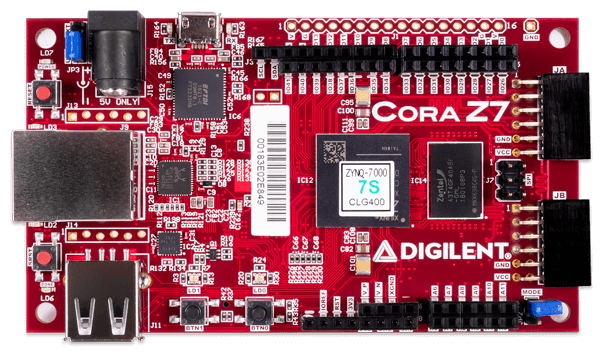
I've started with Arty S7-50 Xilinx Spartan 7 based board.
But once I saw number of resources occupied by soft CPU + DDR controller, and a lot of soldering required to connect audio boards and screen,
I decided to choose different hardware.
Current hardware I'm using
Zybo Z7-10 - $200
https://store.digilentinc.com/zybo-z7-zynq-7000-arm-fpga-soc-development-board/
Waveshare 7" 1024x600 LCD with HDMI interface and touch screen via USB HID -- $60
https://www.waveshare.com/7inch-hdmi-lcd-c.htm
So, overall hardware cost is expected to be $300-$350
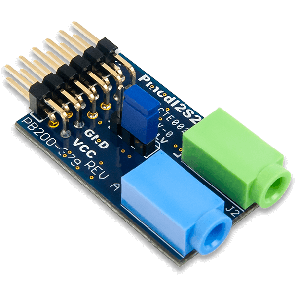
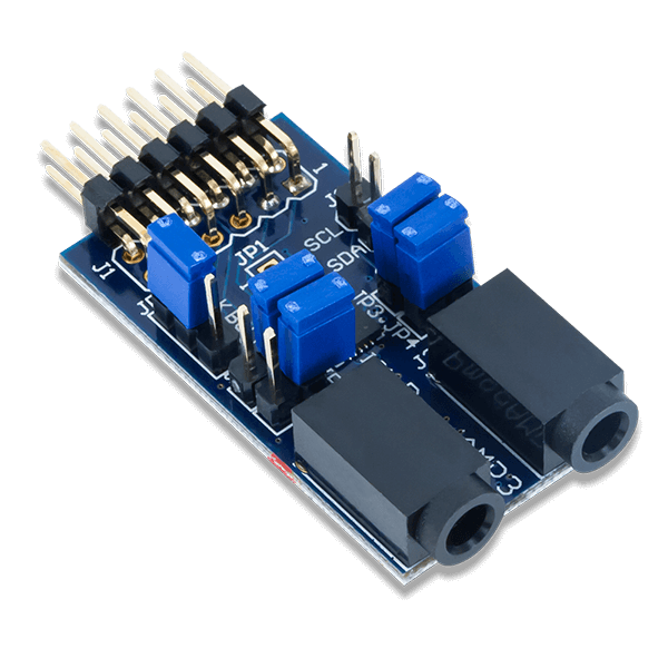
Zybo Z7-10 has on board audio in/out, so no addition audio board purchasing nor soldering is required.
Screen is connected via HDMI and USB connectors - no soldering.
Unlike Dewster's project which uses strange PLL based frequency measurement,
I've decided to use direct measure of oscillator frequency period.
This approach requires oscillator with maximal max/min frequency change on hand movement.
(Minimal capacity in LC oscillator parallel with antenna).
Oscillator is simple single NPN transistor, 74HC invertor to form square form output signal, and ESD protection diodes.
Oscillator frequency decreases by ~5% while hand approaches to antenna.
Two oscillator PCBs are the only part which requires soldering skills.
Outputs of oscillators are 3.3V digital signals which should be somewhere in range 250KHz .. 4MHz.
Oscillator outputs are just connected to two PMOD connector pins.
Parts which are done:
Theremin sensor controller is implemented in FPGA part.
Interface:
2 digital inputs - for pitch and volume antenna oscillator signals
2 digital outputs with generated test signals (for testing purposes may be routed to inputs)
AXI4 Lite slave interface to access controller registers and lookup tables from PS(ARM MCU)
Volume and pitch period direct outputs - may be used by synthesizer
Clocking inputs
ISERDES is used as input for signal period measurement cirquit (1.2GHz effective precision)
4-8 signal period measurement blocks are used to measure the same signal shifted by different delay in delay lines - for oversampling
(adds 2-3 bits)
Both raising-raising and falling-falling edge intervals are measured (adds one more bit to period value)
Total number of signal period bits is near 13-16 depending on oscillator frequency. Precision is equivalent to period measure with ~10GHz base clock.
Measured value is passed to averaging filter with flexible coefficient - goal is to average values for ~ 1 sample interval (48/96KHz).
After filter, we have more meaningful bits of oscillator frequency value.
Once per sample (48000 times per second) controller performs processing cycle.
Measured oscillator signal interval is passed to scaler with MinPeriod and MaxPeriod parameters - setting for near and far hand positions.
Scaler scales input period values from MinPeriod..MaxPeriod interval to 0x000000..0xffffff (out of range values are clamped).
1024x32bit lookup table based interpolator converts scaled period value to linear hand distance (or directly to volume control value - for volume).
For pitch value, there are two more stages:
1024x32bit lookup table based interpolator converts hand distance to note value (fixed point MIDI note number) - applies note range; pitch correction can be applied using this table
1024x32bit lookup table based interpolator converts note value to note base frequency phase increment (alternative point of pitch correction)
Register values and lookup tables are available to CPU via AXI bus interface.
Control registers:
Pitch and volume
Measured period value before averaging filter
Measured period value after averaging filter
Averaging filter coefficient
Scaler MIN and MAX values to specify scaling range
Value after scaler
Value after linearization lookup table
Value after note lookup table (for pitch only)
Value after phase increment lookup table (for pitch only)
2 test signal generator periods and enable/disable flags
Lookup tables content may be modified from PS(MCU) - each is 1024x32bit
Linearization table for Pitch
Linearization table for Volume
Distance to Note table for Pitch
Note to Phase Increment for Pitch
TODOs:
Calculate change detection (e.g. differential) - e.g. to control some synthesizer parameters on volume (left hand) attack/decay.
HDMI framebuffer controller is implemented in FPGA part.
Fixed 1024x600 resolution with 8 or 16 bits per pixel (RGB 322 or 565 pixel format).
Framebuffer address is set via memory mapped register (avaliable from PS/MCU via AXI4 Lite Slave interface).
End of frame (VSYNC) interrupt output
Built in DMA access implementation
Total resources used are several times less than in standard controller from example
GUI library for framebuffer - development in progress
Drawing of primitives and text is implemented
Emulator to test GUI code under windows
Audio output
Built in I2S interface for audio output (24bit, 48 or 96KHz) available from FPGA
Work on audio I/O and mixer IP is not started yet
Synthesizer
Work is not started
As first implementation I'm going to try additive synthesis (SIN lookup table based sine wave generators).
Set of harmonic amplitudes define instrument
Amplitudes and phases may be controlled from by oscillators to get nice sound color.
Current activity: support of touch screen
USB Host driver is required to get touch screen HID reports
There is no out of box implementation of standalone USB Host
Trying to port tinyusb library to Zynq
FPGA resources available after Sensor Controller and HDMI implementation: about 90% - may be used for DSP and audio out.
PS(CPU) resources:
2 ARM cores with floating point support, 533MHz
1Gb DDR RAM
Core 1: common control and GUI
Core 2: DSP (10000 clock cycles per sample at 48KHz) - may be used for some advanced instrument implementations


