D-trigger as heterodine mixer: aliasing

Posted: 3/21/2017 4:15:25 AM
Buggins

From: Porto, Portugal

Joined: 3/16/2017

Hello,


I'm trying to find out suitable osciller and heterodine schematics for digital theremin.

Yesterday I was experimenting with d-trigger in mixer.

Setup:

  • Variable pitch oscillator on unbuffered hex invertor (mostly like in Open.Theremin V3) with separate voltage regulator for power supply. Frequency ~ 500kHz.
  • 10mm copper tube as antenna.
  • Reference pitch - generated by MCU - as 60Mhz / K.
  • Mixer: D-trigger, powered with separate voltage regulator (just in case).
  • Mixer output frequency - somewhere in range 1kHz..10Khz
  • Measurement of frequency - using Teensy 3.6 (ARM based MCU board) - counting number of 60MHz pulses during measured signal interval.

Results were strange. Measured values were jumping in strange way. Some values appeared often, others - never appeared.

Making histogram INTERVAL / COUNT - measured number of 60MHz pulses / count of measurements gives results like


interval count
14879    1
14880    8
14881    25
14999    20
15000    79
15001    2
15119    6
Best: 15000    79
interval count
15001    2
15119    3
15120    102
15121    17
15239    15
Best: 15120    102

There are peaks near some value N and N+1 or N-1 e.g. 15120, 15119 and 15121 (this is expected). But as well there are side peaks - e.g. 15001, 15239. I've modified my program to show new found peaks in histogram while hand is approaching to antenna.


Freq T T(i)-T(i-1)
1605,73 37366 119
1610,86 37247 119
1616,03 37128 119
1621,22 37009 119
1626,45 36890 119
1631,72 36771 119
1637,01 36652 119
1642,35 36533 119
1647,71 36414 119
1653,12 36295 119
1658,55 36176 119
1664,03 36057 119
1669,54 35938 119
1675,08 35819 119

Peaks are distributed equally in distance 119. But what is 119? 60000000/119=504201 - very similar to reference (fixed pitch) clock.

So with D-trigger as a mixer, there is alias - dependence from reference clock frequency. Aliased positions are located in 1-3cm intervals when hand is near antenna. Although it's possible to do some averaging to get measure distributed between aliasing peaks, but it looks ugly.

Why people ever using D-triggers for heterodine mixer? As I see, OpenTheremin.V3 and UNO are using D trigger. OpenTheremin.RC uses XOR mixer.

What is best mixer for digital theremins?

Next time I'll try XOR with 3 stage lowpass filter...


Best regards,

     Vadim


Posted: 3/26/2017 5:32:43 PM
dewster

From: Northern NJ, USA

Joined: 2/17/2012

Vadim, do you have a scope?  I might have asked you this before.  You really need a scope to do this kind of work, otherwise you're feeling your way in the dark.  Hook a scope up to your oscillator and delay the trigger some integer multiple of your mains frequency (to filter out AC hum) and look at the signal.  Is it stable?

You seem to be experiencing much of the same general thing I ran into when developing digital methods of frequency / period capture. There are many ways for quantization to creep in and give you periodic aliasing or sticky points.  I had to add weighted dither noise to the LC drive to eliminate quantized gaps in the phase detection.  The dither basically has to express statistically the intermediate value, and the amplitude of the dither has to span more than one clocked sample period.

Posted: 3/27/2017 6:06:58 AM
Buggins

From: Porto, Portugal

Joined: 3/16/2017

"Vadim, do you have a scope?  I might have asked you this before.  You really need a scope to do this kind of work, otherwise you're feeling your way in the dark.  Hook a scope up to your oscillator and delay the trigger some integer multiple of your mains frequency (to filter out AC hum) and look at the signal.  Is it stable? You seem to be experiencing much of the same general thing I ran into when developing digital methods of frequency / period capture. There are many ways for quantization to creep in and give you periodic aliasing or sticky points.  I had to add weighted dither noise to the LC drive to eliminate quantized gaps in the phase detection.  The dither basically has to express statistically the intermediate value, and the amplitude of the dither has to span more than one clocked sample period."

Hello Dewster!

Thank you for reply.

D-trigger mixer quantization is expected. If you capture D input by C input raising, you should expect that result will be aligned to C input frequencies.


I have only cheap USB oscilloscope - with 8 bit DAC and small memory. So it seems to be useful only in limited conditions. I can see if there is a signal, it's voltage and frequency. But it's hard to see if there some noise, or calculate high precision FFT.


Yesterday, I've tested XOR based mixer. Variable pitch and reference pitch signals are mixed by XOR gate, then filtered with passive 3rd order lowpass RC filter, and then amplified by another XOR gate (working as inverter). While modelling with LTSpice, I see nice smooth sawtooth with amplitude about 90% of input signal on third RC filter stage. But when trying to see real signal with scope, it shows about 30% gain loss per LP filter stage. (Can't it be just influence of oscilloscope input capacity?).


Some photos of my experiments.

I'm trying to use modular design, to try different types of oscillators and mixers.

Digital theremin prototype

Mixer on exclusive or IC. Supports two channels.

XOR mixer

Oscillator.

Oscillator PCB

Results are a bit confusing.

Measured values fit into Gauss distribution with narrow enough peak. But when measured for longer time, I see appearing "side band" peaks with frequency about 80% above and below main frequency. It looks strange and I'm not sure about source of this effect. Probably, it's just caused by bad LP filter design.

Going to try using opamp based LP filter.


Posted: 3/27/2017 12:54:53 PM
dewster

From: Northern NJ, USA

Joined: 2/17/2012

Vadim, you really need a better scope.  I don't own this one (I've got an old Tektronix TDS210) but I'd recommend the Rigol DS1054Z, which can be easily hacked to be a 100MHz scope with FFT and other nice bells and whistles.  A decent scope is absolutely essential for this kind of work, you can instantly and directly see a lot of sensitivity, stability, and hum pickup issues with a good delayed trigger.

What inductor are you using for your oscillator?  I've got some in my parts junk box that look like the one on your oscillator board - ferrite bobbin with heat shrink tubing outside - that don't work at all for series tanks (I got them out of an old audio graphical equalizer).  Too much self capacitance I think.  For parallel tanks probably anything will work, but series tanks are rather sensitive to choice of inductor.  I recommend you get some Bourns 6300 series RF chokes as they work well in just about any kind of oscillator (that doesn't require a winding tap).  It really helps to remove any doubts about the quality of the inductor when doing this stuff.

Using CMOS in linear mode is compelling, though they often don't work as well as the simulation (you need a good linear spice model - good luck with that), and the output waveform can have significant rounding near the rails due to limited open loop gain.  And they can draw significant power when linearly biased.  I researched this and tried several different types out, and am currently using 74LVU04N with 3.3V supply in my digital Theremin.  It is designed to be used this way, and works quite well (as these things go) with decent gain, decently placed input threshold, and small prop delay (important to keep phase error low).

I've played around with heterodyning in digital hardware, and found the XOR with 3rd order low pass (a cascade of 1st order LPF tuned the same) and one high pass section (to kill DC) to work OK in simulation.  The issue is that heterodyning, even if offset (so that there isn't a null in the far field so you can still measure the frequency or period) produces a rather wide range of frequency output, so you get large amplitude differences due to the filter attenuation, which is maybe OK in digital, but will make analog thresholding more difficult and noise prone.  A 3rd or higher order tracking bandpass filter would be ideal here but beats me how to build it.  Even though offset heterodyning with period measurement can give fantastic linearity in the right scenario, I gave up on heterodyning and hope I don't have to revisit it.

A more straightforward digital signal extraction might be to drive a series or parallel tank with a fixed frequency (at resonance) and use an XOR gate to detect the phase between the drive and the tank response.  This gives you a nice digital (or analog if you integrate) signal that you can easily measure.  But you will likely still have to dither the drive to remove dead spots in the playing field (easily done in an FPGA, not sure how you might do this with a processor).  Averaging / filtering won't kill aliasing once it creeps in.

Using processors to do these kinds of capture and measurement directly can be problematic, which is why I'm using an FPGA (where I use DDR I/O to get ~400MHz resolution).  You might end up using a tiny FPGA to do the front-end work and sending the digital data to the processor via serial link (rather like the Theremino which uses a dedicated processor: link, link, link about 1/2 way down the page - their oscillator is good).

Even though you are likely copying the open.theremin oscillator, it may have issues.  As I stated, it doesn't have enough voltage swing at the antenna, and 50/60Hz mains hum intermodulation is much more likely when that is the case.  This might be a partial cause of your strange data.  You can probably get the oscillator topology to swing higher with a capacitive divider.  Post a link to a LTSpice sim of your oscillator and I can probably help you with that.

Posted: 3/27/2017 1:57:51 PM
Buggins

From: Porto, Portugal

Joined: 3/16/2017

I'm using Bourns RLB0914-102KL, 1000uH R=2.1 Ohm, Q=55 -- it's what I've managed to find. Will try to find where to buy 6300 series.

What is better solution for oscillator active component than unbuffered hex inverter? Did you try using opamps?

Currently I'm trying hex inverter based oscillator with 9V Vcc and ~60V voltage on antenna. (Hope to get better results than I had with 3.3V power and 3.6V on antenna).

Does it make sense to use high Vcc (3/6/9/12V) for oscillator / heterodine / filter?

I'm using 180MHz ARM which cannot be used for direct measuring of oscillator frequency, but I hope that it can precise measure heterodine output frequency (2..10KHz). I'm planning to average 2-10 values (all measures collected since last frame) to get frequency for next audio frame frequency sweep.

Did you see any strange aliasing with XOR + filters heterodine?


Posted: 3/27/2017 2:16:00 PM
dewster

From: Northern NJ, USA

Joined: 2/17/2012

"What is better solution for oscillator active component than unbuffered hex inverter? Did you try using opamps?"  - Vadim

A single transistor works OK, either low VT NFET or NPN.  Opamps have too much propagation delay which give phase error and thus lower tank voltage swing.

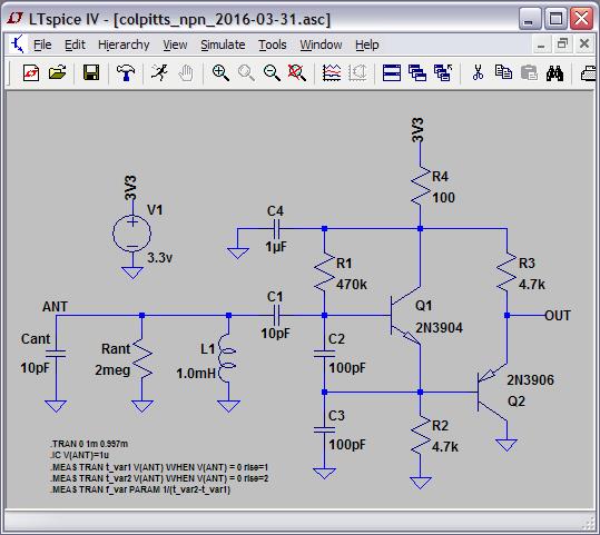
Why don't you give my NPN / PNP Colpitts a try (LTSpice):

Cant and Rant aren't real components, they are standing in here for the antenna in simulation.  Should give 30Vp-p or more at the antenna.  Just about any small signal transistors should work.  Draws ~0.5mA so it's great w/ battery power.

"Does it make sense to use high Vcc (3/6/9/12V) for oscillator / heterodine / filter?"

With a high Q tank you can get hundreds of volts swing with a 3.3V supply (and ~2Vp-p drive via simple emitter follower drive).  3.3V XOR should work fine, not sure about the filter.

"Did you see any strange aliasing with XOR + filters heterodine?"

Not in Excel / System Verilog simulation, but that's as far as I took it.

Posted: 3/27/2017 4:10:17 PM
Buggins

From: Porto, Portugal

Joined: 3/16/2017

Thank you very much! I'll try transistor based oscillator.

Are you sure R=100 Ohm + 1uF in power supply is enough to avoid noise from other components? Does it make sense to add separate voltage regulator?

Does your schematics require some components for ESD protection?

Would placing of oscillator to separate small PCB and mounting it near antenna help to achieve better results than if placed on main pcb?

Does it make sense to tweak parameters of your oscillator to get output closer to pure sine wave?

Posted: 3/27/2017 4:35:01 PM
dewster

From: Northern NJ, USA

Joined: 2/17/2012

"Are you sure R=100 Ohm + 1uF in power supply is enough to avoid noise from other components? Does it make sense to add separate voltage regulator?" - Vadim

I use a separate regulator for each antenna circuit, the small TO-92 ones work well here.  If it's the only oscillator on the regulator it probably doesn't need as much (if any) in the way of RC power supply filtering.  The transistors are alternately on, so the current draw is fairly constant. 

"Does your schematics require some components for ESD protection?"

No, but you could add a Littlefuse SP721 to the base of Q1.  Also it is best to insulate the antenna, the thicker the insulation the better.

"Would placing of oscillator to separate small PCB and mounting it near antenna help to achieve better results than if placed on main pcb?"

I would locate the oscillator near the antenna and use the low impedance output of Q2 to rout the signal back to the main board.  My digital Theremin uses Ethernet cabling here, which supplies power, one drive signal, and two sense signals.  If you use something like the SP721 for ESD, you can connect some of the pins to this external cabling to protect it against ESD too.

"Does it make sense to tweak parameters of your oscillator to get output closer to pure sine wave?"

The signal at the antenna is pretty pure, the signal at the buffer isn't so much on the upper portion.  It all depends on what you'll be doing with the signal.  You could feed it to a CMOS inverter through a small C and with large R feedback (maybe 100pF & 220k, to center the threshold) to square it up.

Posted: 3/27/2017 5:27:17 PM
Buggins

From: Porto, Portugal

Joined: 3/16/2017

In your LTSpice model there is no series resistance specified for inductor. Does it affect performance?

Posted: 3/27/2017 7:25:12 PM
Thierry

From: Colmar, France

Joined: 12/31/2007

These unbuffered inverter oscillators are evil. Lots of low frequent phase modulation because of the RC components in the feedback path which adds a second oscillation.

You might get these somewhat better by biasing the input at VDD/2 from a buffered voltage divider instead of using that xMeg resistor from the output back to the input.

You must be logged in to post a reply. Please log in or register for a new account.