


I got my first theremin seven years ago, my good friend built PAIA Theremax for me. This was more project out of initerest for me and my friend as he was hi-end hi-fi tube electronics builder and I am accordionist. We discussed briefly about tube vs transistor theremin sound, but didn't do any research on this topic as I didn't played theremin very much. Over the last year I have looked a bit more into this subject and discovered some interesting things. First lets look some assumptions about RCA tone:
* RCA specific sound is created by tubes.
* RCA specific sound is associated with RCA theremin oscillators and heterodyne mixer type.
* RCA specific sound is impossible to create with transistor theremin.
These all are correct to some extent but... back then circuit design philosophy was very different and clever tricks were used to reduce component count and overall cost - cost was high back then. Older electronics books describe how to use single transistor in AM radio to amplify, detect RF and also amplify audio signals at same time. I don't have access to RCA theremin for measurement and trial, but I have access to schematic and some waveform pictures. Looking to RCA theremin schematic I noticed very big difference between its design and more modern tube theremin designs - RCA lacks negative grid bias on all stages! If oscillators produce sine waves and mixer puts out sine like wave, then VCA, pre amp and power amp - all without bias voltage - flatten and square off one half of waveform, as can be seen from waveform picture. After discovering that I got an idea! What if I try to just generalize and approximate RCA sound instead of chasing ideal waveform(if it exist at all)? I left mixer stage alone and concentrated only to end result. I looked waveform picture and generalized it to square wave with ~25% duty cycle. Transformers in RCA theremin acted like band pass filters.
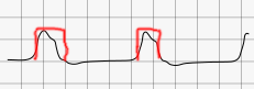
Then I did simple listening test with synthesizer with square wave, width set to 25% duty cycle and to my surprise it sounded very similar to RCA theremin. With low-pass filter at output it got softer and smoother at upper range still buzzing at low register. By the way, fast rising and falling edges are what gives buzzing characteristic to sound. This is why Moog style diode based asymmetric clipping waveshaper gives very mellow and smooth sound - it doesn't create fast edges. Now base benchmark was established. Next thing was to implement it somehow to Theremax. Luckily PAIA designers had done much of hard work already. Theremax has very interesting timbre circuit design, it doesn't create nice tone at all, but it is base on what I designed my circuit. Theremax uses voltage comparator IC as Schmitt trigger to create square from sine like soundwave. I implemented same circuit on breadboard, but I added reference voltage adjustment for comparator and pre amp to boost Theremax signal from ~100mV RMS to 6V P-P. Adjusting reference voltage did exactly what I needed - it changed square wave duty cycle! Then I continued with refinements and discovered that comparator IC is very well usable but overdrive voltage must be taken into account - it is problematic at low duty cycles. I just added simple transistor switch to put out square wave at region where comparator is not fully overdriven and gives weird half-sine output. Here is schematic of my design.
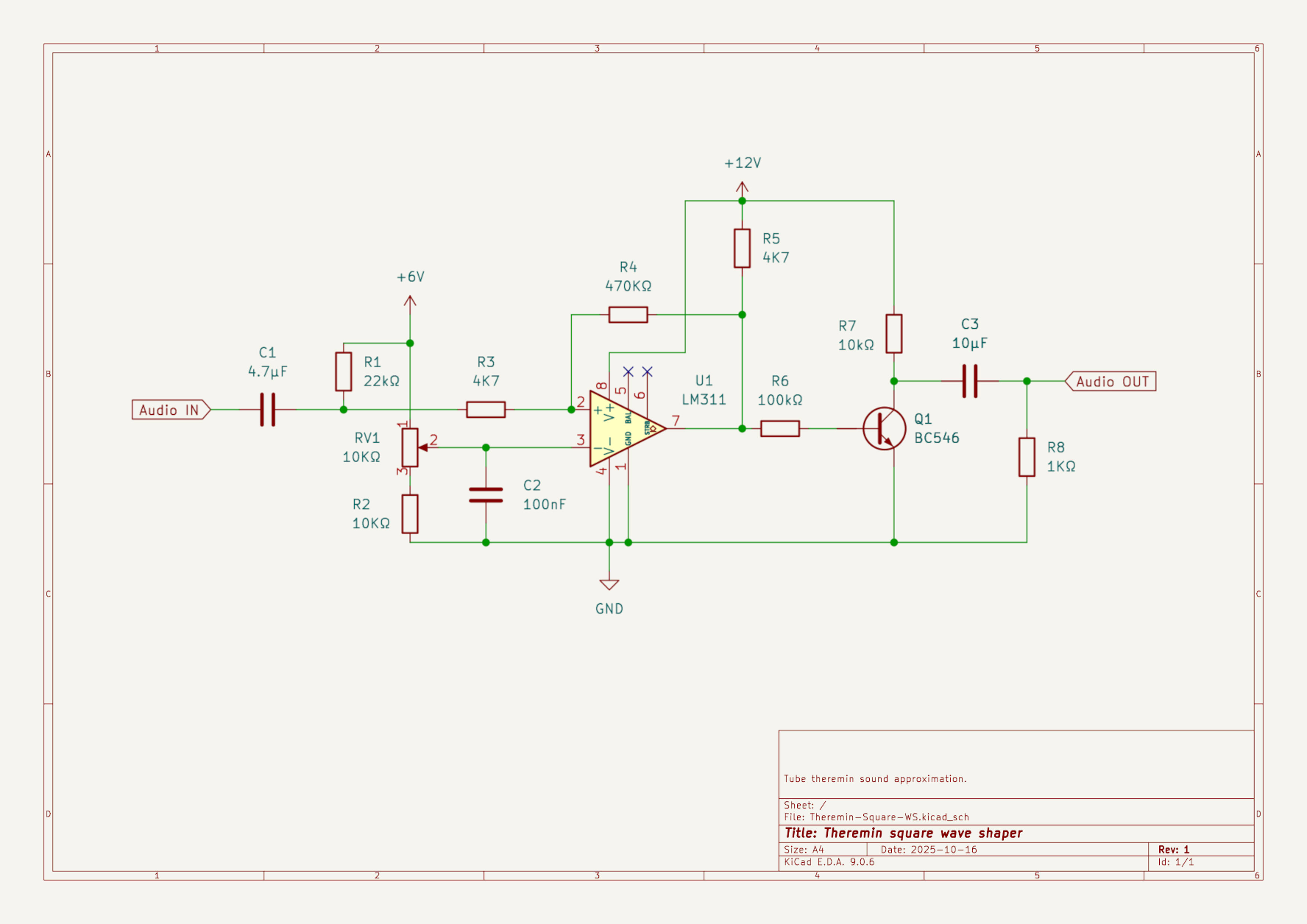
Component values can be adjusted as needed. Audio level is expected to be 6V P-P. Ideally this type is circuit is driven from triangle wave with stable amplitude, but Theremin sine like wave does the job with sufficient results. In schematic there is no low-pass filter at output, but on my implementation I added simple one at ~2kHz - without it sound is harsh and bright. Most important thing about this design is its simplicity - no exotic components, no precision tuning. Simplicity may very well make it commercially viable solution for theremins. Other big advantage is flexibility - it can be added as an extension to any theremin and also retaining instruments original sound.
Some technical but interesting scope pictures
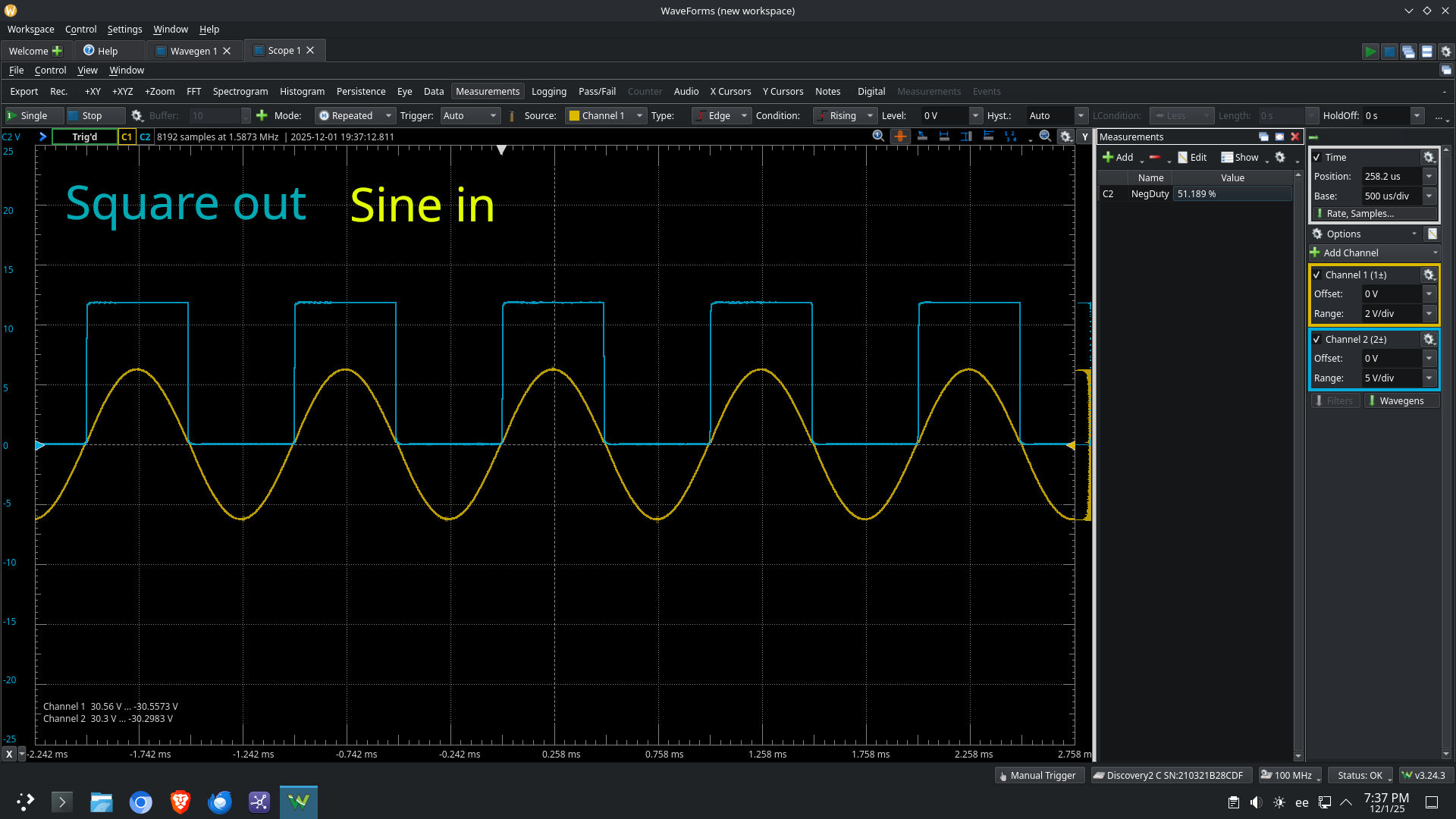
Square output at different reference voltages resulting different duty cycles.
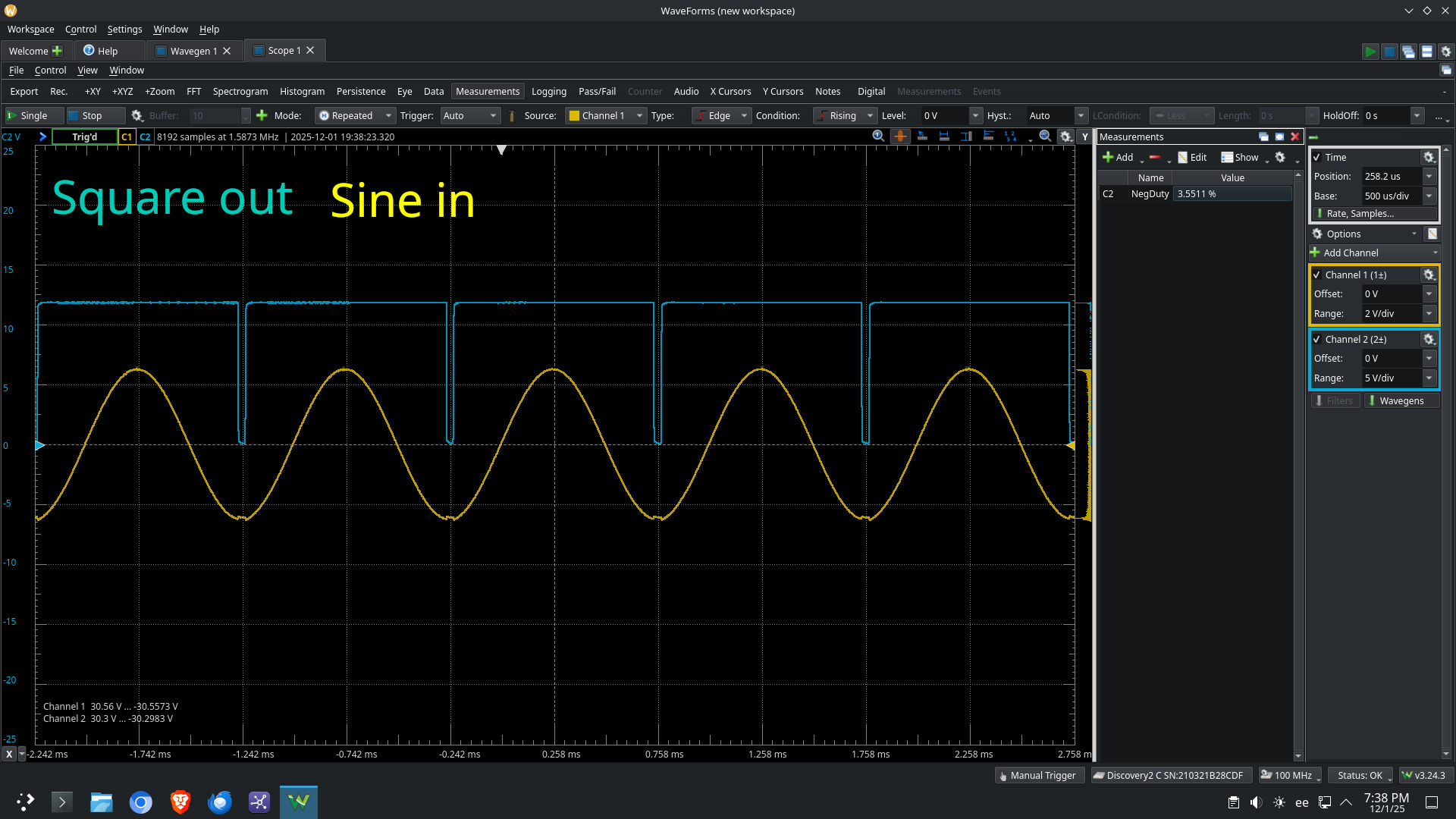
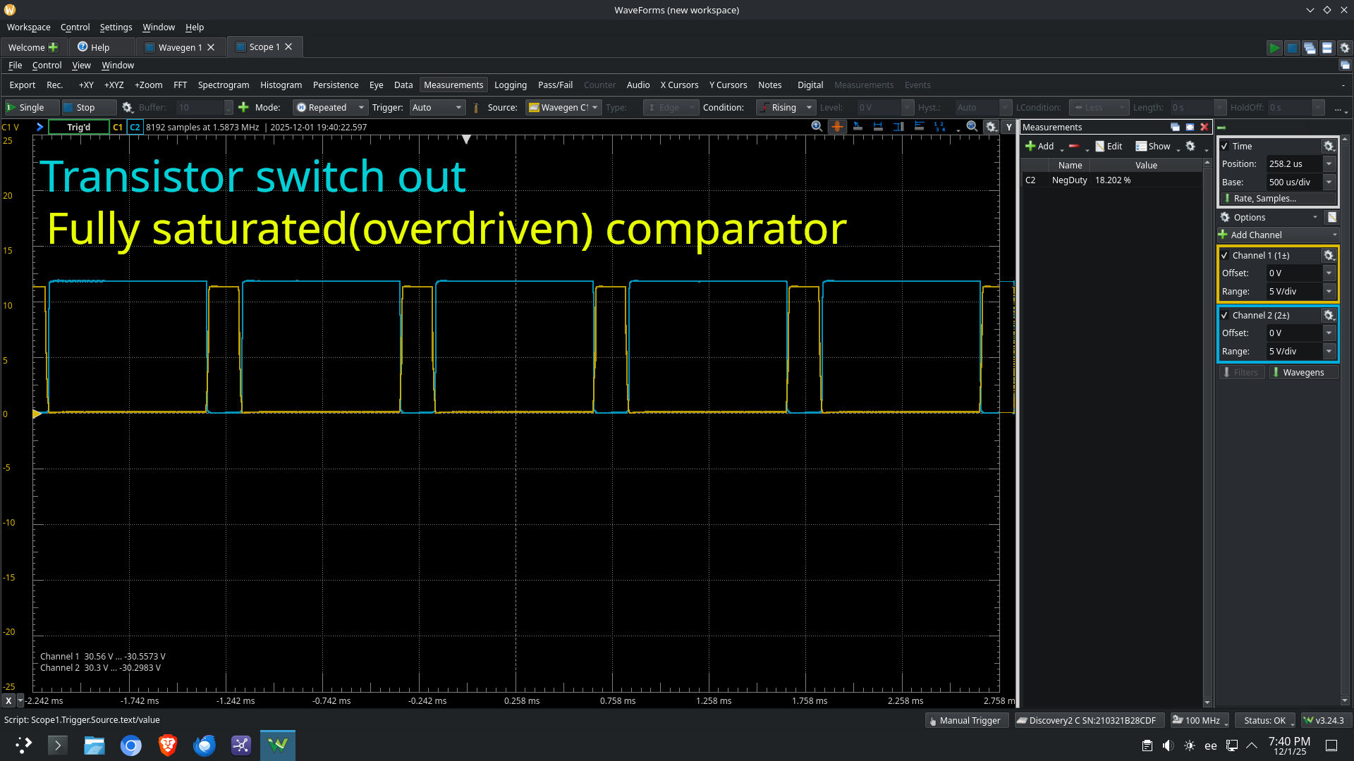
Comparator and transistor switch output at overdrive region.
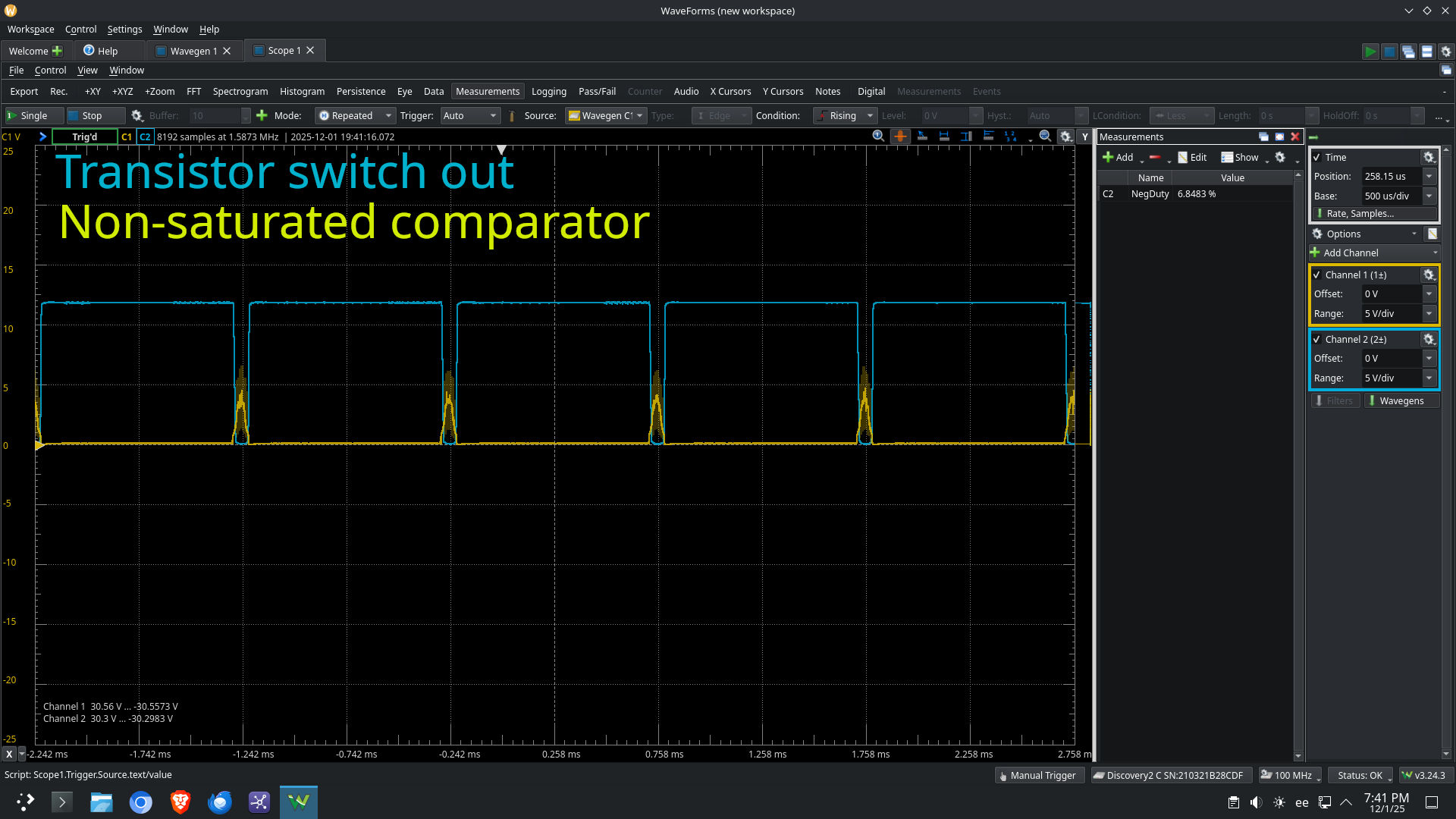
Comparator and transistor switch output at non-overdrive region.
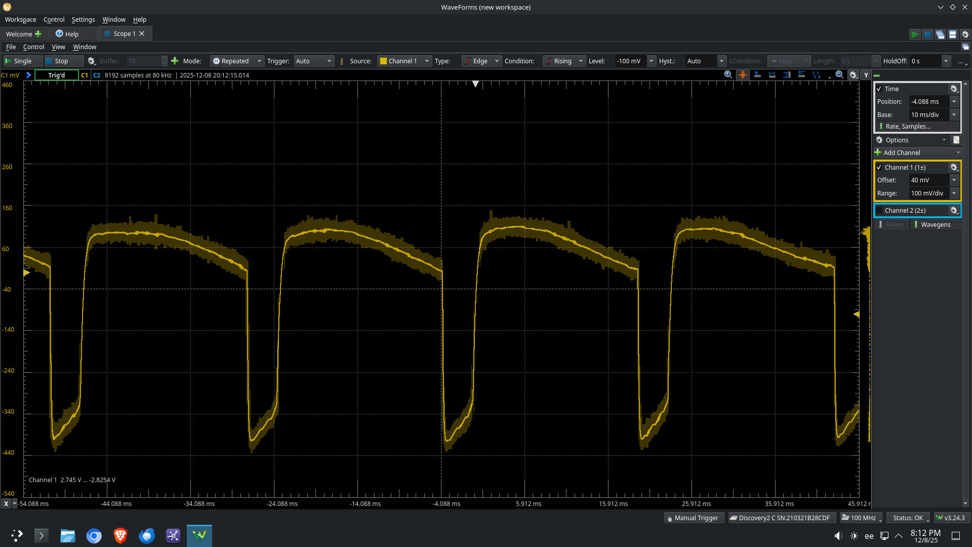
Waveform after low-pass filter
Now most important part - Video and sound examples. I used cheap 12 inch Harley Benton guitar cab as speaker.
Conclusion: If designers at PAIA had discovered this back then, I'm sure that Theremax had been much more popular than Moog Etherwave.
Happy experimenting


 First time I saw it I was like "waaa?" Lately I've been interacting with someone who inherited a Theremax and he reported that desoldering the braids largely fixed the drift.