Theremin simulator

Posted: 3/8/2025 10:04:59 AM
ILYA

From: Theremin Motherland

Joined: 11/13/2005

New version (v1.22) of Theremin Explorer is avalible now. Download page is here.

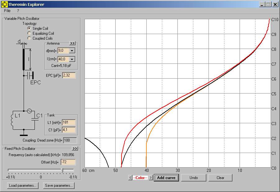
The new version incorporates the ‘frequency pulling’ effect. The magnitude of this effect is controlled by the ‘Coupling: Dead zone’ parameter. When saving parameters to a file, this corresponds to the line ‘Fcoupling=’.

The simulation assumes that there is no hysteresis effect (the lock range is equal to the hold range, and the approach to the synchronization point is ‘soft’). For basics refer to topic

In reality, the hold range is always larger than the lock range, and synchronization can occur slightly earlier – a ‘hard jump.’ This is due to the oscillator’s increased sensitivity to noise and interference in the immediate vicinity of the synchronization region.

Posted: 3/8/2025 10:40:53 AM
ILYA

From: Theremin Motherland

Joined: 11/13/2005


I wonder how this will affect the curves.

In the figure below, the black line represents the Etherwave musical scale without accounting for the coupling effect (as if the oscillators were completely decoupled):

The orange curve shows the effect of adding coupling, but with the Pitch control left unchanged. Note that the zero-beat point has moved closer to the antenna. The Pitch control was then adjusted to restore the original position of the zero-beat point (red line).

Is the coupling an improvement or not? It’s a complex question. On one hand, the length of the linear portion in the mid-frequency range has increased. This is due to a reduced sensitivity of the instrument to hand movements (i.e., the octave length has increased – it’s now around 10 cm versus 8 cm). On the other hand, the non-linearity of the bass range has drastically increased (the slope of the curve is steeper).

Similarly, for the Korolyov's (2003) theremin:

I think that overall, it’s a matter of personal preference.

Posted: 3/8/2025 12:16:47 PM
dewster

From: Northern NJ, USA

Joined: 2/17/2012

"On one hand, the length of the linear portion in the mid-frequency range has increased. This is due to a reduced sensitivity of the instrument to hand movements (i.e., the octave length has increased – it’s now around 10 cm versus 8 cm)."  - ILYA

IMO, reducing the pitch field sensitivity without significantly impacting linearity makes for an easier to play instrument and is therefore a noble goal.  And substantially reducing the sensitivity makes for an entirely different instrument.  I reduce mine to roughly 1/2 of "normal" analog Theremin sensitivity which allows me to easily play standing up without a brace or chair, and breathe, squirm, etc. while doing so.  This of course precludes "normal" aerial fingering technique, but with heavily reduced sensitivity it seems less necessary?  There is so much analog expectation surrounding the Theremin, which of course is to be expected, but it's been rather bewildering for this developer to deal with.

ILYA, a bit of the artwork is missing, but your sim works in Linux Mint!

[EDIT] ILYA, could you perhaps add a "linearity" graph to your sim which shows the derivative (slope, sensitivity) of the response?  It's a bit hard seeing how linear it is and the level of sensitivity on the response graph.

Posted: 3/8/2025 7:53:18 PM
ILYA

From: Theremin Motherland

Joined: 11/13/2005


"could you perhaps"

That makes sense. I should try that. But if all else fails, there’s a function to export the curve’s data points to a text file, which can then be analyzed in Excel.

Posted: 5/6/2025 6:20:30 PM
ILYA

From: Theremin Motherland

Joined: 11/13/2005


The new version (v2.24) features a mode for drawing sensitivity curves. This allows for a more visual comparison of the linearity of theremins. The figure below shows the sensitivity curves of an Etherwave ST (black line) and a typical “single-coil” theremin (red line).

The unit of sensitivity is octaves per decimeter (10 cm) of hand movement. Within the comfortable playing range, this is approximately 1 octave/dm.

The new version is also optimized for running under Linux Mint (thanks to dewster for testing).

I would like to remind you that the program uses capacitance data taken from measurements of real antennas. The data has been smoothed, but due to the finite precision of the measurements, slight “jaggies” are still possible (noticeable only in the sensitivity curve drawing mode).

Posted: 5/8/2025 12:14:56 AM
oldtemecula

From: 60 Miles North of San Diego, CA

Joined: 10/1/2014


Hello Ilya,

Your avatar or TW date of joining is my birthday, coincidence, I do not think so.

Did you get a chance to see my Electrodeum TW post for a "parallel" pitch antenna circuit that has ideal pitch field linearity? When it resonates it is either on or off, there is no almost linear. It adds to the "authentic" theremin sound enhancing the RF wave shape for a happy theremin.


Save this PDF for the future generation when they become dis-illusioned by Artificial Intelligence & Digital Imitation.

https://www.oldtemecula.com/+Pitch%20Field%20Linearity2.pdf


Christophe S Becher

Posted: 5/8/2025 8:53:41 PM
dewster

From: Northern NJ, USA

Joined: 2/17/2012

"The new version (v2.24) features a mode for drawing sensitivity curves. This allows for a more visual comparison of the linearity of theremins."  - ILYA

ILYA, you should get some kind of award for creating and publishing this amazing tool!  Linearity and sensitivity are much more obvious now, thank you for adding that feature!  You've captured the essence of many models too, which is pretty fantastic!

I gave most of them a spin (in Linux Mint!) and it seems the EW (red) & EPro (green) are the most linear, and almost identically so:

I wonder if you could comment on how the physics of segmenting the linearizing coil into multiple chokes, as is done with these two Theremins, works out?  The EPro in particular has one of the most complex linearization schemes.  Evan Kahn disassembled the arm of his EPro and reported this to me:

  Inside is a string of coils in series:

  LC tank drive
  11mH (with trimcap in parallel with it)
  4.7mH
  11mH
  11mH
  Antenna

  Total of ~38mH

  Current value of the trimcap is on the order of 4.7pF

So the full mH seems a bit off, and that trimcap might complicate things?

Not trying to make more work for you, but wondering if you might entertain accommodating digital linearization schemes, such as that in the D-Lev (which uses an inverse fractional power of the LC frequency), and perhaps the Open Theremin (which I believe uses an offset LC period measurement)?  It would be neat to see how they compare to their analog brethren.

Posted: 5/12/2025 7:32:41 PM
ILYA

From: Theremin Motherland

Joined: 11/13/2005

Dewster, If you’re referring to the very first Open Theremin, which was built using an RC oscillator, then yes, it would be interesting to model it behavior (and similar theremins with RC oscillators) to compare them with theremins based on LC oscillators. I need to think about how to do this simply, without overloading the program’s interface.

As for digital theremins, I give up on that. They are a “black box” to me, with an unknown linearization algorithm. Of course, I could dig into the code (if that’s even possible) and see how it all works, but is it worth doing if the algorithm can change at any moment?

Fortunately, the fundamental laws of physics on which analog theremins rely don’t change so quickly.

Regarding serially connected inductors:

While the total inductance is clear (except in cases where their mutual inductance contributes when the coils are close together), difficulties can arise when estimating the “self-capacitance” of the chain.

The method of “serially connected individual Cself” doesn’t work here. I have experimented with chains of coils several times and obtained paradoxical results. In some cases, the resulting Cself was less than the Cself of a single coil, and in others, it was greater. Only one rule works: the self-resonant frequency of the chain is always lower than the self-resonant frequency of any of the individual coils.

Since Cself doesn’t really exist (it’s just an equivalent), it makes sense to refer to the root cause for calculations: the standing wave in the long conductor that makes up the coil (or chain of coils). LTSpice allows modeling serially connected “long transmission lines” (each coil can be replaced by such a “long line”). If the parameters of each line are set correctly, we get a more or less plausible result regarding the final “self-resonant frequency.” From SRF, you can then obtain the final Cself.

But it seems to me that for determining SRF (Cself), it is more reasonable to simply conduct in-kind tests (generator + oscilloscope + a few minutes of time).

Posted: 5/12/2025 7:44:01 PM
ILYA

From: Theremin Motherland

Joined: 11/13/2005

"my Electrodeum TW post" - Christopher.

The ancient Egyptians built pyramids to perpetuate the memory of themselves (or maybe they were just passing the time?). We build theremins and post descriptions in free access. The main thing is to maintain the hosting of our ‘pyramids’ for as long as possible.

Posted: 5/13/2025 8:37:00 PM
dewster

From: Northern NJ, USA

Joined: 2/17/2012

"Regarding serially connected inductors: While the total inductance is clear (except in cases where their mutual inductance contributes when the coils are close together), difficulties can arise when estimating the “self-capacitance” of the chain."  - ILYA

Yes, my limited experiments here turned out to have more complex results than I would have guessed.

"As for digital theremins, I give up on that. They are a “black box” to me, with an unknown linearization algorithm. Of course, I could dig into the code (if that’s even possible) and see how it all works, but is it worth doing if the algorithm can change at any moment?"

The LC model would be your single coil case (i.e. no series inductor).  The heterodyning would be a simple constant subtraction (K0), which I'm guessing your program is already treating this as (sans coupling)?   The rest is similarly simple math:

  Pitch (linear) = K4 + (-K3 * [-K2 + (K0 - Freq)^K1 ] )

Note that K0 is generally greater than Freq so that the difference increases as the hand approaches the antenna.

K1 is a negative fraction, somewhere between -0.25 and -0.33.  Since a negative power is a reciprocal, this makes the result decrease as the hand approaches the antenna.

K2 pulls the curve down to the X axis, K3 scales the sensitivity and reverses the sense because it is negative, K4 pushes the curve back up.  The result is linear, and would therefore need exponentiation to translate to pitch as the logarithmic human ear hears it.  A spreadsheet to show what's going on (the power is accomplished via log2 & exp2, which is how it is done in the D-Lev software):

  https://d-lev.com/research/theremin_linearization_2022-11-09.ods

So your sim would need K1 thru K4 added, which seems a bit excessive I suppose.  Is your C vs. hand distance data published anywhere?

(edited for errors)

You must be logged in to post a reply. Please log in or register for a new account.