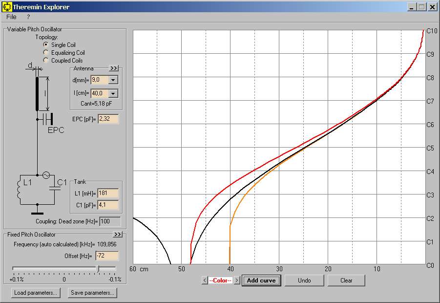
Dewster, If you’re referring to the very first Open Theremin, which was built using an RC oscillator, then yes, it would be interesting to model it behavior (and similar theremins with RC oscillators) to compare them with theremins based on LC oscillators. I need to think about how to do this simply, without overloading the program’s interface.
As for digital theremins, I give up on that. They are a “black box” to me, with an unknown linearization algorithm. Of course, I could dig into the code (if that’s even possible) and see how it all works, but is it worth doing if the algorithm can change at any moment?
Fortunately, the fundamental laws of physics on which analog theremins rely don’t change so quickly.
Regarding serially connected inductors:
While the total inductance is clear (except in cases where their mutual inductance contributes when the coils are close together), difficulties can arise when estimating the “self-capacitance” of the chain.
The method of “serially connected individual Cself” doesn’t work here. I have experimented with chains of coils several times and obtained paradoxical results. In some cases, the resulting Cself was less than the Cself of a single coil, and in others, it was greater. Only one rule works: the self-resonant frequency of the chain is always lower than the self-resonant frequency of any of the individual coils.
Since Cself doesn’t really exist (it’s just an equivalent), it makes sense to refer to the root cause for calculations: the standing wave in the long conductor that makes up the coil (or chain of coils). LTSpice allows modeling serially connected “long transmission lines” (each coil can be replaced by such a “long line”). If the parameters of each line are set correctly, we get a more or less plausible result regarding the final “self-resonant frequency.” From SRF, you can then obtain the final Cself.
But it seems to me that for determining SRF (Cself), it is more reasonable to simply conduct in-kind tests (generator + oscilloscope + a few minutes of time).


