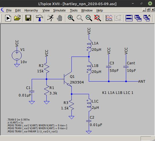
For a couple years I have been working on replicating and studying Buchla modular electronic instruments with a colleague at University of Michigan. We have thoroughly built and studied multiple modules from this system, however one specific schematic has us a bit perplexed. I was wondering if I could pick the collective brains of Theremin World since RF and theremin circuits are not an area we have much experience in.
Attached is the only scan of the schematic we have:
The 117 Proximity Detector is a module that has two detachable antennas so the performer can use both hands to adjust frequency of two separate oscillators. It would appear that this circuit is using the Hartley oscillator as the basic building block for both the primary and secondary oscillator. The problem is, the schematic does not clarify much about the coils used. I have spoken to a synthesizer tech about this, and even after trying some of his suggestions, we have not made much headway.
Our tech friend suggested that the coil shown in each oscillator is a tapped coil that is possibly coupled between the emitter circuit of the hartley and the collector, so he made a part suggestion. The coil we ended up using was a Coilcraft SWB-2010-1-PCL, datasheet located here:
https://www.mouser.com/datasheet/2/597/swb-1223867.pdf
It would be noted that one aspect of the project we are working on is keeping things as original as possible so we can study the module fully as it would have been in 1969, so we don't need a polished circuit, but one that works... I think there is an issue with the coil we used - can anyone kindly take a look at this circuit and see if there are any issues that we might be missing?


