Building Teensy 3.6 based digital theremin

Posted: 3/27/2019 8:16:42 AM
Buggins

From: Porto, Portugal

Joined: 3/16/2017

Yet another digital theremin project thread...


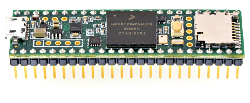
I'm working on digital theremin project based on Teensy 3.6 MCU.

Not as powerful as dewster's FPGA based project, but has much better capabilities than OpenTheremin.

I believe it's easy to build DIY project.

Teensy 3.6 MCU board:

32 bit 180 MHz ARM Cortex-M4 processor with floating point unit.
1M Flash, 256K RAM, 4K EEPROM
Programming using Arduino IDE.


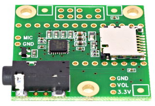
Audio adaptor based on SGTL5000 audio chip.
It has line IN / OUT and headphones output.


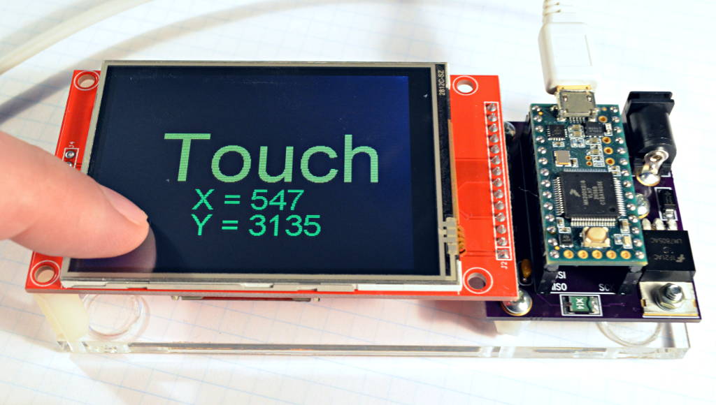
2.8" LCD with resistive touch screen on ILI9341 display controller and XPT2046 touch controller:


MCU allows to generate reference clocks for pitch and volume using MCU timers: f = 60MHz / K
This makes theremin sensor pretty simple. No external reference frequency oscillator is required.

Frequency of sensors output may be measured with precision of 60MHz timer.


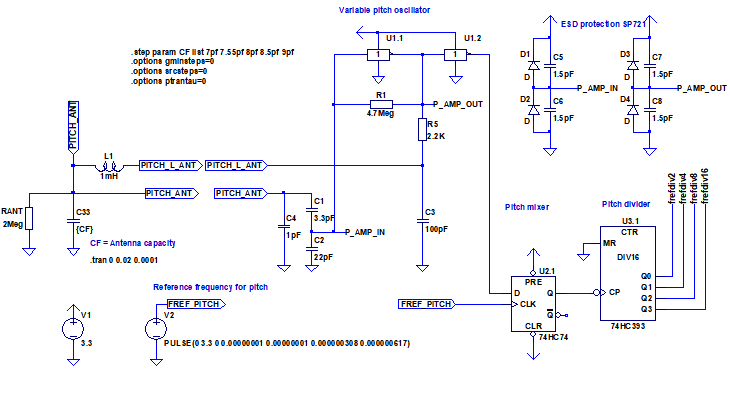
Theremin sensor is pretty simple.

Two oscillators based on unbuffered hex inverter similar to OpenTheremin oscillators schematics,
but tuned to have big antenna voltage swing (~30V) and high sensitivity (frequency changes by 7-8% while hand moves between far and near range).

D trigger based mixer increases 5..7% of high (1..2MHz) frequency change to  300..500% of medium (16KHz..90KHz) frequency change.
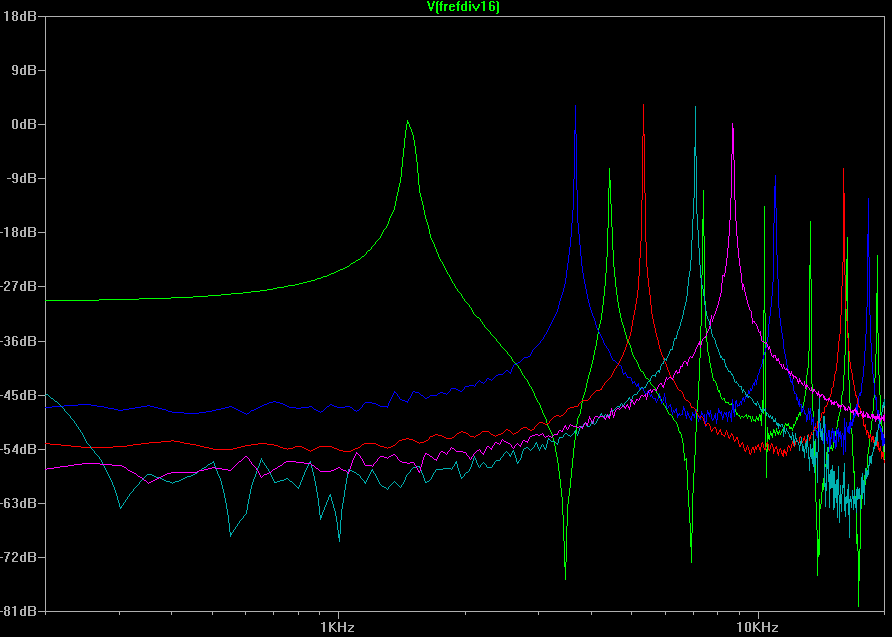
1/16 divider does some averaging and decreases of mixer frequency to easy measurable range.

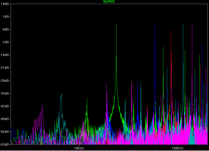
LTSpice model:

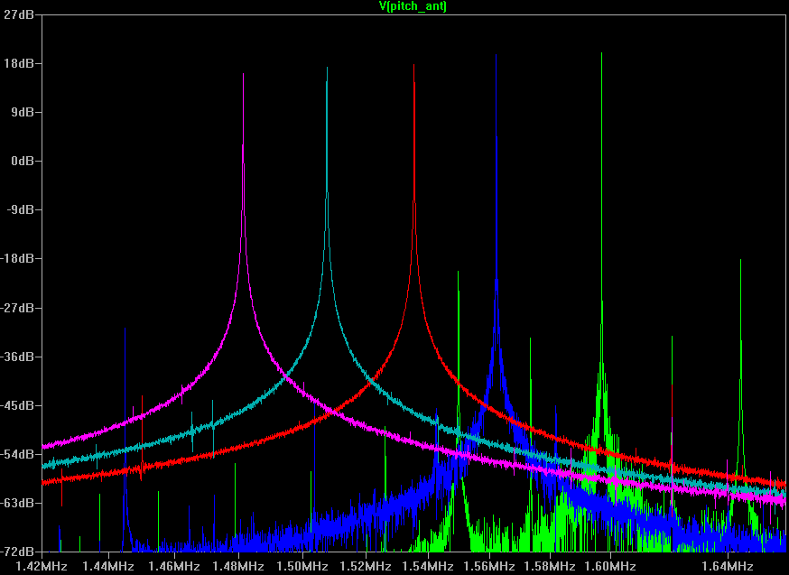
LTSpice simulation:
When antenna capacity increases from 7 to 9pF, oscillator frequency decreases from 1.6MHz to 1.48MHz

After mixer, hand movements when hand is far from antenna becomes more visible:

Divider output:


Simulation results table:


Code:
Antenna capacity:  7pF      7.55pF    8pF      8.5pF     9pF
Oscillator freq:   1.6MHz   1.56MHz   1.54MHz  1.51MHz   1.48MHz
Mixer frequency:   23.6KHz  58.7KHz   85.2KHz  113KHz    140KHz
Divider output:    1.5KHz   3.6KHz    5.3KHz   7KHz      8.6KHz

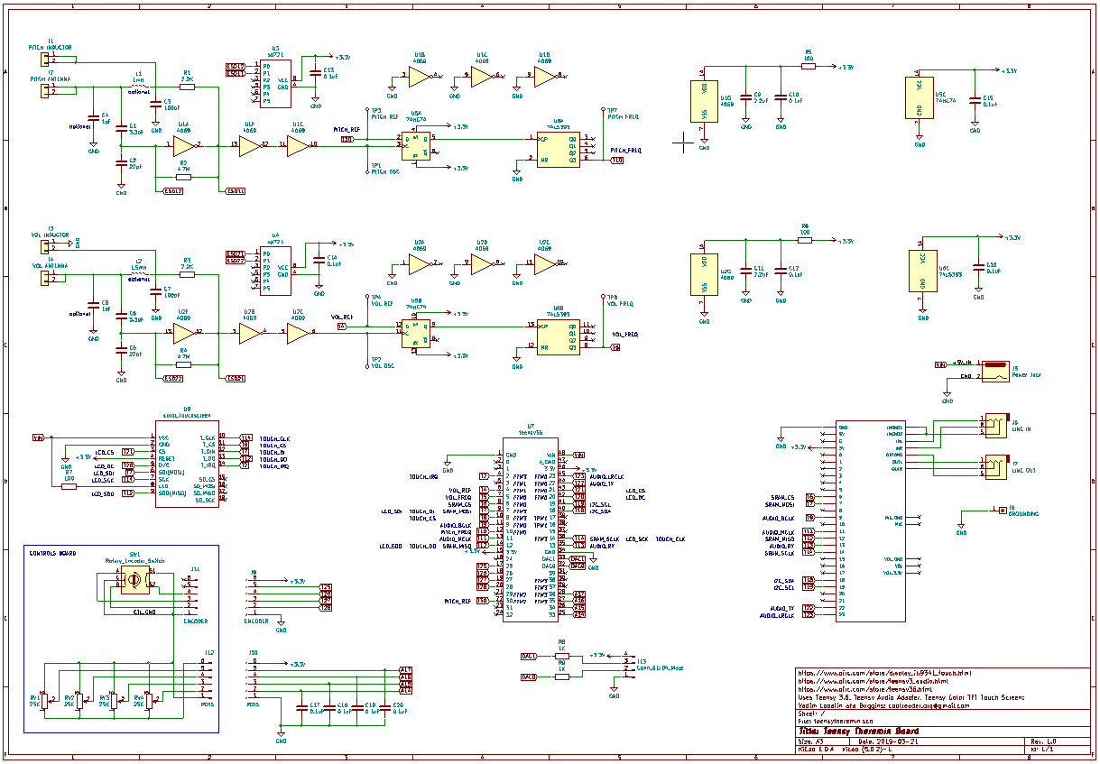
Full schematics (pdf): 


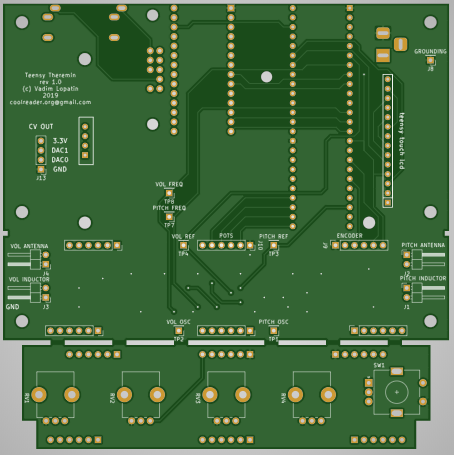
As a hardware controls, there are 4 pots and one encoder with button.
One of pots will be used for headphones volume control.
3 remaining pots - to control instrument parameters and effects (e.g. vibrato, reverb, etc.)

2 DAC outputs may be used for CV out (although they are 3.3V).

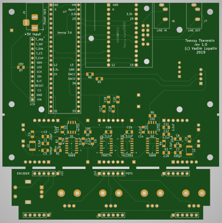
PCB:


Waiting for ordered PCBs...

Posted: 3/27/2019 7:15:08 PM
dewster

From: Northern NJ, USA

Joined: 2/17/2012

"Not as powerful as dewster's FPGA based project, but has much better capabilities than OpenTheremin.
32 bit 180 MHz ARM Cortex-M4 processor with floating point unit.  1M Flash, 256K RAM, 4K EEPROM"  - Buggins

Hive is 32 bit, 180MHz, but doesn't have floating point, nor anywhere near that amount of RAM or Flash, so you're way ahead there.  But the FPGA logic offloads much of the housekeeping (oscillator logic; LCD, Tuner, SPDIF, UART), and gives 400MHz timing resolution.  Having EEPROM large enough to hold SW and presets is nice, though I'm sure you could use Flash for that.  What I really like about Hive is that it is 100% deterministic in terms of timing (no cache, no speculative execution, etc.) and the timing model is super simple.  There's no overhead for subroutines either due to the hybrid register/stack arrays, so I feel pretty free to factor my code when writing assembly.

I see you're using an RC to drive the LC tank.  I was experimenting with this too at one point, but abandoned it due to the frequency based phase shift and attenuation, though it does work well.  Have you considered the 74AHC04?  Of the 74AHC parts I've tested, the Vt has been remarkably well centered at VCC/2.  And they're natively 3.3V and quite fast (less phase shift, less temperature drift).

You'll probably want to debounce that encoder via RC, and then debounce the hell out of it in SW.  I've found mechanical encoders to be really weird and fussy when spun fast (they can go backwards!).  They wear quickly wear too, so you have make the interface as bullet-proof as possible.  I've spent weeks, perhaps months, just on encoder nonsense.

Looks like an interesting project, thanks so much for sharing the details, please keep us up-to-date!  Digital Theremin circuitry can be really simple and very robust.  I'm not sure why the Open.Theremin was never taken to this next level by its creator.

Posted: 3/28/2019 7:31:48 AM
Buggins

From: Porto, Portugal

Joined: 3/16/2017

Hive is 32 bit, 180MHz, but doesn't have floating point, nor anywhere near that amount of RAM or Flash, so you're way ahead there.  But the FPGA logic offloads much of the housekeeping (oscillator logic; LCD, Tuner, SPDIF, UART), and gives 400MHz timing resolution.  Having EEPROM large enough to hold SW and presets is nice, though I'm sure you could use Flash for that.  What I really like about Hive is that it is 100% deterministic in terms of timing (no cache, no speculative execution, etc.) and the timing model is super simple.  There's no overhead for subroutines either due to the hybrid register/stack arrays, so I feel pretty free to factor my code when writing assembly.

AFAIK, HIVE has 8 threads, so isn't it 180MHz*8 actually?
Didn't you consider upgrading to next gen FPGA, with more resources?

I hope, 256KB of RAM will be enough for implementing of reverberation. I believe reverb is must have for theremins. My Etherwave after applying of external reverb using guitar combo sounds much better.

Teensy 3.6 based implementation will require only two time critical IRQs: measurement of theremin sensor output frequency (fired on signal edge, should read 60MHz timer value latched on signal edge, and do some accumulation and averaging) and synthesis of audio frame (frame size is expected to be about 3ms, measured frequency from sensor will be converted to note/volume only once per frame, then interpolated).


I see you're using an RC to drive the LC tank.  I was experimenting with this too at one point, but abandoned it due to the frequency based phase shift and attenuation, though it does work well.  Have you considered the 74AHC04?  Of the 74AHC parts I've tested, the Vt has been remarkably well centered at VCC/2.  And they're natively 3.3V and quite fast (less phase shift, less temperature drift).

I've played a bit more with LTSpice simulation and found that RC is really needed at front of LC tank.

R may be reduced to increase antenna voltage swing.

Code:
.step param R5 list 50 100 200 500 1000 2000 4000
Cant = 7pF   C3=100pF
R5, Ohm   50     100    200    500    1000   2000   4000
Vant      42.35  41.55  39.93  37.75  36.14  33.89  30.43

R=100..200 looks as best choice for me. It makes sense to use 100 Ohm or 1000 Ohm resistor since such components already present in schematic.

Playing with various C values gave a bit strange result.
Increasing of C gives bigger voltage swing on antenna, but may lead to unstable generation.
It looks like C=100..300pF is good choice. Original value in schematic, 100pF, is good enough

Code:
.step param C3 list 1pF 10pF 33pF 100pF 200pF 500pF 1000pF
Cant = 7pF  R5=200 C3=1pF 10pF 33pF 100pF 200pF 500pF 1000pF
C3,pF     1     10    33     100    200    500    1000
Vant      3.63  7.98  17.35  39.69  50.58  60.14  60.45
Fosc,MHz  2.048 1.82  1.677  1.593  1.568  1.54   1.52

Checking how C affects sensitivity (difference between oscillator frequency for Cant=7pF and 9pF)

Code:
.step param C3 list 1pF 10pF 33pF 100pF 200pF 500pF 1000pF
Cant = 7pF  R5=100 C3=1pF 10pF 33pF 100pF 200pF 500pF 1000pF
C3,pF     1     10    33     100    200    500    1000
Vant      3.88  8.47  18.59  41.32  51.2   63     56.15
Fosc,MHz  2.03  1.8   1.666  1.59   1.569  1.54   1.53

Cant = 9pF  R5=100
C3,pF     1     10    33     100    200    500    1000
Vant      2.9   6.59  15.5   35.5   48.8   63     60.5
Fosc,MHz  1.959 1.711 1.557  1.472  1.448  1.42   1.4
F7pf/F9pf 1.045 1.064 1.077  1.082  1.082  1.084  1.086

Last row shows sensitivity of oscillator to changes of antenna capacity.

It was a surprise for me to see that even big C values at LC tank input do not affect sensitivity, just decrease oscillator frequency (till some limit near 1.4MHz)

C in range 100..300pF looks reasonable choice. It gives 8..8.5% of frequency changes.
Finally, R=100 and C=330pF gave voltage swing 63V which almost does not decrease when hand approaches antenna, with frequency change 9% when Cant varies between 7pF and 9pF.

Additional change of LC tank output capacitive divider parameters from 3.3pF/22pF to 1pF/10pF gives 110V voltage swing and 11% of frequency change.

Of course, 74AHC can be used as a replacement, once they have soic-14 package.
They just not as popular / easy to buy than 74hc.

You'll probably want to debounce that encoder via RC, and then debounce the hell out of it in SW.  I've found mechanical encoders to be really weird and fussy when spun fast (they can go backwards!).  They wear quickly wear too, so you have make the interface as bullet-proof as possible.  I've spent weeks, perhaps months, just on encoder nonsense.

I din't try reading from encoder yet. It was my mistake that RC filters are not included into current schematics. Now I just hope s/w debouncing will be enough.
BTW, what R and C values are the best for encoder output filtering? I believe you did a lot of experiments.

Looks like an interesting project, thanks so much for sharing the details, please keep us up-to-date!  Digital Theremin circuitry can be really simple and very robust.  I'm not sure why the Open.Theremin was never taken to this next level by its creator.

Still using slow 8bit Arduino UNO while much better MCU may be found at the same price looks really strange.


BTW, forum engine support of quotes seems to be broken
Posted: 3/28/2019 8:29:40 AM
Buggins

From: Porto, Portugal

Joined: 3/16/2017

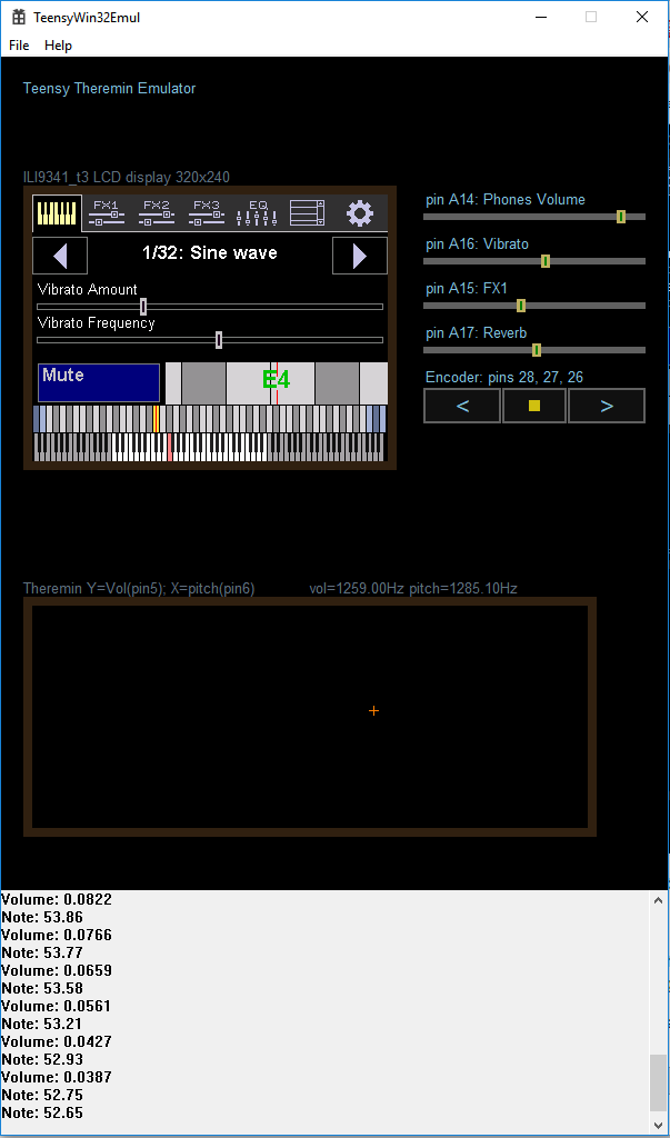
Software development directly on device is quite tricky.

I wrote emulator (can be built using Visual Studio for win32) which simplifies development.

Arduino IDE sketch is being built into win32 application and is running in separate thread.
Theremin Sensor output is replaced with values from emulator sensor panel (up = hand far from volume antenna, down = hand close to volume antenna, left = hand far from pitch antenna, right = hand near pitch antenna).
Audio IRQ is simulated, output of synthesizer is fed into windows wave out device.
analogRead(), digitalRead() outputs are substituted with values from emulated controls.
ILI8341 library interface is implemented as emulation drawing requested primitives on screen.
Touch library is emulated too, mouse down/up/move are routed via touch library.
Serial output emulation puts everything sent to serial console to the bottom of emulator window.


I wrote uGUI library for UI, which is pretty simple but enough for implementing theremin UI.

On screenshot you can see on-screen pitch preview and working note range selection items.

Bottom line with piano keys is not only showing current note and note range, but can be used to control range using touch. Touch+move near begin or end of range allows to change one side of range, while touch+move near center of range allows to move the whole range.

Control above piano keys shows current note (fractional) inside selected range

One more control is a tuner - pitch preview.


Current S/W state allows to test synthesis and GUI, playing "theremin" using mouse. Although, mouse is not suitable control for playing.
I'm planning to add Wacom Tablet support for theremin sensor input simulation which would provide really usable replacement for theremin sensor.

Posted: 3/28/2019 12:49:21 PM
dewster

From: Northern NJ, USA

Joined: 2/17/2012

"AFAIK, HIVE has 8 threads, so isn't it 180MHz*8 actually?
Didn't you consider upgrading to next gen FPGA, with more resources?" - Buggins

No, it's 180MHz / 8 threads = 22.5MHz / thread.  Coding in assembly makes the most efficient use of the limited horsepower and memory, but it's time consuming.

I've looked around for other FPGAs, the new Cyclone 10 could be promising as it consumes less power and has one less voltage supply.

"I hope, 256KB of RAM will be enough for implementing of reverberation. I believe reverb is must have for theremins. My Etherwave after applying of external reverb using guitar combo sounds much better."

256KB / 2 / 48k = 2.6 seconds of 16 bit delay.  Higher quality reverb algorithms use 32 bit values, so 1.3 seconds.  My feeling is that isn't enough.  Any delay-based effects gobble up the memory.

"I've played a bit more with LTSpice simulation and found that RC is really needed at front of LC tank."

The RC is absolutely necessary because it (ideally) gives a 90 degree phase shift.  The LC tank at resonance gives another 90 degrees, and the inverter gives 180 degrees, for a total of 360 degrees, hence oscillation.  The problem is the RC can at most give 90 degrees, and that's where it's really attenuating the drive signal.  So the swing is either reduced because the LC tank is having to provide more phase shift than 90 degrees (a phase error) or the drive signal is being attenuated a lot.  Amplitude reduction due to phase error gets worse with higher Q coils, and the RC is frequency dependent, so I reluctantly abandoned this oscillator topology, though it can probably be tuned to specific coils and antenna capacitances and work well.

"BTW, what R and C values are the best for encoder output filtering? I believe you did a lot of experiments."

I'm actually debouncing 100% digitally, but it takes a fair amount of high speed logic to do this.  I didn't do any experimenting on this, but datasheets can offer recommendations (two R's and one C per pin).  I have no idea how much RC can tame the problems encoders have.  I'm hugely oversampling at 180MHz with a gray code state machine, running this to a wide counter with hysteresis limits, accumulating this at 48kHz, and sub sampling the result at the 14Hz, with a polynomial for velocity and (this is important to limit reversing) a velocity limit.  Small diameter knobs let the user spin the encoder really fast, which is where most of the problems happen, particularly with wear.  A brand new encoder may act perfectly fine for a month or more and then start acting up, which is disturbing.

"BTW, forum engine support of quotes seems to be broken"

To get rid of the crazy formatting, edit your post and click on the "greater than less than" View Source button all the way to the right (I can't use the symbols themselves because they are treated as formatting!) and delete the formatting codes.  Any time you paste (even if you are copying & pasting from inside the post!) you must be in the View Source mode or unwanted formatting codes will be generated.  Ctrl+Shft+S is another way to toggle View Source mode in the editor.

Posted: 3/28/2019 5:45:02 PM
Buggins

From: Porto, Portugal

Joined: 3/16/2017

"I've looked around for other FPGAs, the new Cyclone 10 could be promising as it consumes less power and has one less voltage supply."

Interesting devices, with SDRAM

Altera/Intel:
MAX1000 16 KLE with 32 MByte SDRAM   EU40
CYC1000 25 kLE, 66 Memory blocks (9K), 594 Memory blocks (Kb), 18 x 18 multipliers -> 66  EU35

Xilinx:
S7 Mini Spartan S7 - 25K cells, 8MB HyperRAM, EU40

Lattice ECP5: (coming soon)
TinyFPGA EX  24/84K cells, 28/156 multipliers, 100/500KB block ram, 8MB Hyper RAM, 16MB flash  price is unknown so far


Awesome chinese device on unknown FPGA - if it's really usable.

Licheetang Anlogic EG4S20  20K LU, 130KB SRAM, 8MB SDRAM, a lot of pins  $17.9 on seedstudio

Posted: 3/28/2019 8:02:58 PM
dewster

From: Northern NJ, USA

Joined: 2/17/2012

"MAX1000 16 KLE with 32 MByte SDRAM  EU40"

I haven't looked all that closely at Max devices lately, but I do have actual experience with them.  We used earlier ones to replace CPLDs.  Internal configurator Flash makes them expensive.

"CYC1000 25 kLE, 66 Memory blocks (9K), 594 Memory blocks (Kb), 18 x 18 multipliers -> 66  EU35"

Interesting.

"Lattice ECP5: (coming soon)
TinyFPGA EX  24/84K cells, 28/156 multipliers, 100/500KB block ram, 8MB Hyper RAM, 16MB flash  price is unknown so far

Awesome chinese device on unknown FPGA - if it's really usable.

Licheetang Anlogic EG4S20  20K LU, 130KB SRAM, 8MB SDRAM, a lot of pins  $17.9 on seedstudio"

I have actual experience with Lattice as well, last time I used the toolset it was nowhere near as good as Altera/Intel or Xilinx.  The SW tools are much more important than the FPGA silicon!  For this reason I'd be wary of Anlogic as well, though I have no experience there.

Here are a couple of boards I've been looking at:
https://www.ebay.com/itm/10CL006-Mini-Board-Altera-Intel-Cyclone-I0-FPGA-with-onboard-USB-Blaster/113204959711
https://www.ebay.com/itm/EP4CE22-Mini-Board-Altera-Intel-Cyclone-IV-FPGA-EP4CE-with-onboard-USB-Blaster-/113631918536

If this one came with a larger FPGA I could utilize the SDRAM for reverb and such:
https://www.ebay.com/itm/QMTECH-Intel-Alter-FPGA-Cyclone-10-FPGA-10CL006-Development-Board-32MB-SDRAM/173494149008

Posted: 4/1/2019 7:44:00 AM
Buggins

From: Porto, Portugal

Joined: 3/16/2017

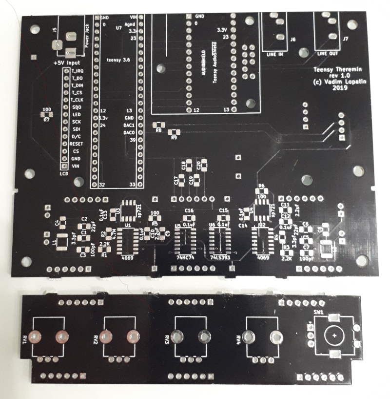
Got my PCBs earlier than expected.
Black color mask, like Open.Theremin

Still waiting for SMD components.

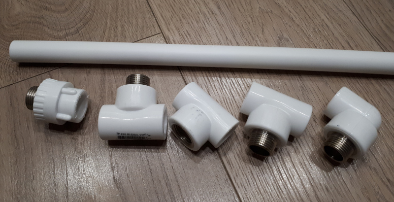
So far, I'm working on antennas mounting construction.
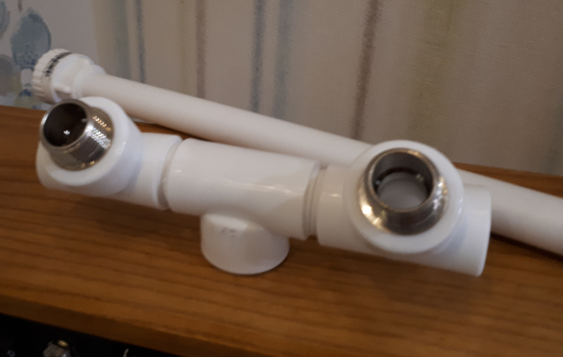
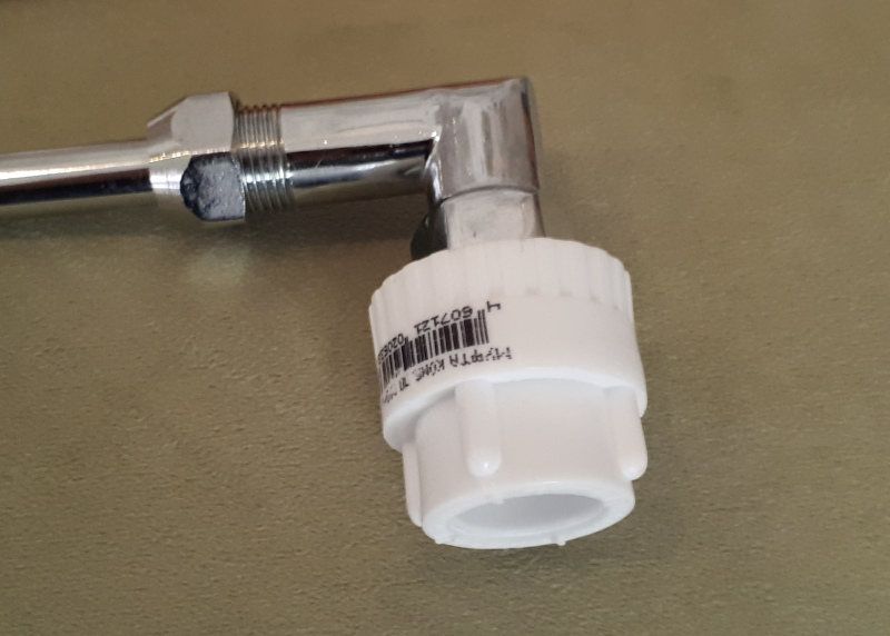
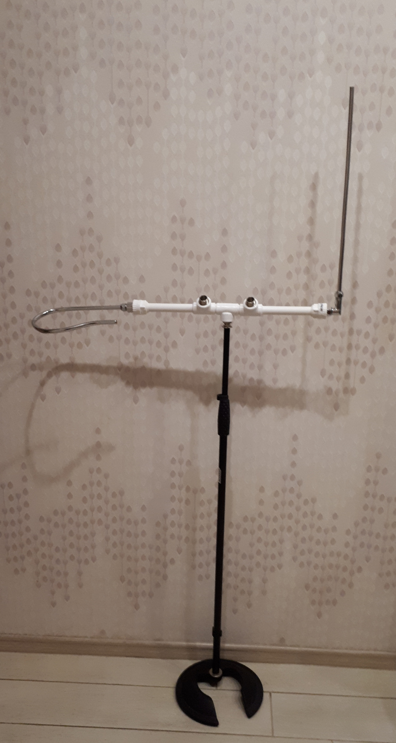
Etherwave-like plumbing technology goes deeper.
Adding more polypropylene fittings and pipes.

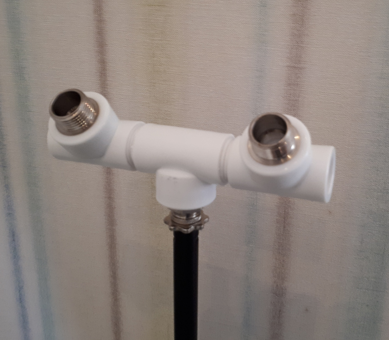
Fittings assembled under some angle will allow to mount cabinet with better viewing angle, and easier access to controls.

Middle fitting is for mic stand mounting, and can be used for attaching of some table stand. (Simple solution: drill some plastic dish and mount it).
Mic stand mounting requires 1/2" pipe thread to 3/8" mic stand thread adapter (it's hard to find one). Although, even 3/8" water pipe thread adapter can be used.

Antennas will be mounted using 1/2" male or female fittings (depending on available antennas).

Center of weight should be located at the point of mic stand mount.

Attach antenna mounting fittings on tube so that distance between antennas is about 40cm, mount antennas, find center of mass,
cut pipes and attach piece with three middle fittings so that distance between antennas is preserved and center of mass is above mic stand mount fitting.

Small cabinet with theremin will be mounted using two 1/2" holes with 110mm between them.


Posted: 4/1/2019 3:11:00 PM
Buggins

From: Porto, Portugal

Joined: 3/16/2017


Code:
If this one came with a larger FPGA I could utilize the SDRAM for reverb and such:

https://www.ebay.com/itm/QMTECH-Intel-Alter-FPGA-Cyclone-10-FPGA-10CL006-Development-Board-32MB-SDRAM/173494149008


Isn't 6k LEs too few? Even SDRAM controller will occupy big part of it (e.g. 1000-2000cells).
What is LE count of your current hardware?

Xilinx board from the same shop: Spartan 6 with 8MB of SDRAM and 14.5K logic cells for $22

BTW, Xilinx LE is bigger than Altera or other vendor LEs.
LUTs are 6inputs/1-2 outputs, and one LUT is associated with two D-triggers vs one D-trigger in other FPGAs.
So, more complex designs can be implemented using the same number of LEs.

Posted: 4/2/2019 5:35:44 PM
dewster

From: Northern NJ, USA

Joined: 2/17/2012

"Isn't 6k LEs too few? Even SDRAM controller will occupy big part of it (e.g. 1000-2000cells).
What is LE count of your current hardware?"  - buggins

I'm currently using a Cyclone4 EP4CE10, which has 10k LEs.

"Xilinx board from the same shop: Spartan 6 with 8MB of SDRAM and 14.5K logic cells for $22"

Interesting, thanks!  Here it is for a bit less:

https://www.ebay.com/itm/Xilinx-XC6SLX16-Spartan-6-FPGA-development-board-32Mb-SDRAM-memory/112642078755

"BTW, Xilinx LE is bigger than Altera or other vendor LEs.
LUTs are 6inputs/1-2 outputs, and one LUT is associated with two D-triggers vs one D-trigger in other FPGAs.
So, more complex designs can be implemented using the same number of LEs."

Yes, the LUT I/O can vary, making the LE count an apples-to-oranges comparison.  LUT I/O count "tunes" the logic for certain applications, some will go faster, but if all the I/O aren't utilized then LUT resources are wasted -  it's a waste / speed tradeoff.

Historically, Xilinx used to have no block RAM resources but instead used LUTs for RAM, which gobbled them up like crazy and made them rather slow due to all the interconnect (interconnect wire delays usually dominate total delay in a path).  Xilinx was also slow to adopt true PLLs for clock managment, instead relying on DLLs which were less feature-rich.  Though Altera's had their problems too.

In the past, I've found Altera parts to have higher top speed and to be less expensive than Xilinx, though perhaps that has changed.  Also, IIRC the Xilinx tools weren't taking SystemVerilog as well as the Altera tools, and SV is really, really nice to use.

Xilinx has always struck me as rather like Intel: snooty and overpriced.  Kind of weird that Intel bought Altera.

You must be logged in to post a reply. Please log in or register for a new account.