CAUTION - I make absolutely no guarantees for this circuit mod, use at your own risk! - CAUTION
I'd like to present my Etherwave Standard (EWS) low frequency mod. It was inspired by the existence and performance videos of Thierry's ESPE01 board but isn't a reverse engineering of his undoubtedly excellent offering. It’s merely what this or any other average EE might likely do when confronted with the oscillator coupling issue that plagues the EWS. I hope no one here thinks I am in any way trying to encroach upon or steal any of the well deserved thunder of the ESPE01 or Thierry's efforts - quite the contrary.
In the stock configuration the EWS fixed and variable pitch oscillators are mixed via two 15 pF capacitors feeding a diode, which causes coupling between the oscillators. This coupling creates a dead zone around zero beat which has a some good points. For one it helps to keep the instrument silent if you move far away from it. For another it helps to prevent operation on the other side of zero beat, where moving away from the antenna produces an increase in pitch. Finally, the coupling alters the wave shape in the bass region to a rather pulse-like string sound that some may find useful. However, coupling has several bad points. The worst is that it restricts the operation in the bass range. The low end behaves rather non-linearly as the coupling increases with decreased frequency, making control down there difficult. And the tone gets very thin sounding before it poops out. In my opinion the bad effects of coupling far outweigh the good and I can't imagine ever wanting to revert my EWS back to stock.
The circuit is basically just two non-inverting buffers formed from simple emitter followers. The impedance that the capacitors from the LC tanks (C6 & C2) see is fairly high (~100k) so as to not limit their swing too much. Mixing then takes place on the emitter side, where the transistor beta mostly isolates the loads from the sources. Slightly larger capacitors are used on the mixing side to boost amplitude a bit. If you hear "motor boating" (ba-bup ba-bup ba-bup) when playing frequencies very near zero beat you should adjust the 10k pot away from center and try again. I experienced this slightly with the bread boarded version, but the final version employed a different set of transistors that are likely better matched because no adjustment was necessary. In most cases you can probably dispense with the pot and just make the emitter resistors 10k each. You could probably also balance the mixer by replacing the 100k resistors with 47k resistors, lifting their grounded ends and connecting them to either side of a 100k pot with the wiper at ground, though I didn't pursue that method at all.
+/-12V and ground are available at the 8 hole inline expansion point on the Etherwave, and this is where I located the prototype board. C6 and C2 were removed from the EWS board with a solder sucker and iron, the capacitor legs were then bent outwards 45 degrees, so that they form a 90 degree angle with each other. One leg of C6 was then resoldered at the position where it came from, in the hole closest to the edge of the board, with the free leg of the capacitor pointing towards the prototype. Same for C2 (solder it into the hole closest to inline expansion point). Two 22 gage wires were then run from the free legs of the two caps to the prototype, and a third to the free hole at the C2 location (closest to the center of the board). Because these capacitors are directly connected to the sensitive side of the LC tanks you'll want to keep these wires short and direct. I constructed the prototype on a piece of glass epoxy vector board (I don't recommend the phenolic kind that Radio Shack sells as the foil tends to delaminate when soldering) and used the leads from some old LEDs to solder it 1/2" or so above the expansion point (they are stiffer than regular wire). Don't position it too high or it might interfere with the top of the EWS case when closed.
The jumper allows you to switch between pre mod and post mod operation. Obviously the buffers are still in circuit so this isn't a complete reversion with the jumper installed, but it sounds very close to me - certainly there is coupling going on in the bass region with the jumper installed and very little or none with it removed. Store the jumper on one of the pins when not needed. You can purchase special square pin headers, but I instead used the snipped off leads of an old LED here for jumper pins.
If you might sell your EWS at some point in the future you're probably better off with Thierry's ESPE01 mod. It's likely better thought out and certainly better constructed, and you'll be able to point to various web links and YouTube videos of it in action to your prospective buyers, thus enhancing its value. If you think you might want to go easily back to mostly stock response with a simple jumper change, and feel like a bit of hacking, you might want to give my circuit a shot. I recommend you set it up on a breadboard and try it out before you fully commit, this lets you back out of the mod easier if you don't like it, and gives you the chance to play around with the circuit topology and values. Who knows, maybe you'll stumble across something you'll like better!
Now for some pix!
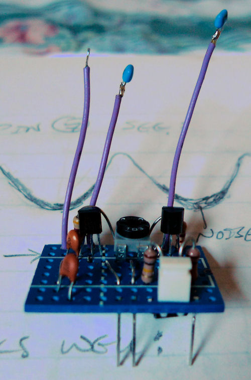
Above is a view of the prototype with C2 and C6 already soldered to the ends of the wires. Those are snipped off LED leads poking out the bottom for mounting.
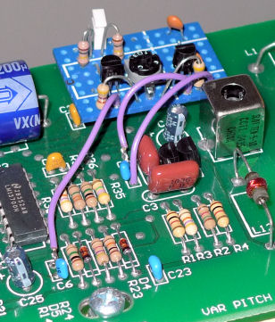
Above is the prototype soldered in position. You can see here how one lead of C6 & C3 are soldered back to the main board, and the third wire goes to the empty hole at C3.
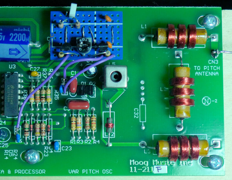
Above is a more arial view of the install. Note the jumper is on a single pin for storage.
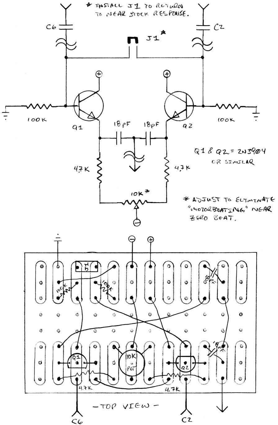
Above is the schematic and how I decided to do the vectorboard layout. This is an x-ray view of the vector board looking down from the top (the copper pads are on the bottom).
============
[EDIT - 2014-04-04]
If you experience "motorboating" or a "ba-BUP ba-BUP" sound near 0 Hz (the null point), you should try decoupling both of the collector leads independently as FredM suggests:
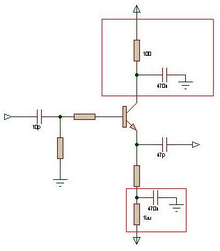
The top box shows a 100 ohm series resistor going from the positive rail to the collector, and 0.47 uF from collector to ground. So for the two transistors in the mod you would need two resistors and two capacitors. This fix reportedly worked for TW member Marekbuk.

