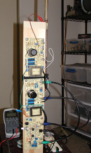
For my winter challenge project this year I’ve decided to build a tube Theremin staying reasonably close to the RCA/Lev-built designs ca. 1930 while using new/current production vacuum tubes and other parts. As this happens to be the most active hive of theremin enthusiasts I’d like to get some feedback from those of you who have done vacuum tube theremin builds to see what you all think of my plan and it’s feasibility.
Background
I'm a tube amplifier guy who has dabbled in radio work so most of the concepts in the theremin are familiar to me. I'm 100% confident I could build a functional instrument using period tubes & schematics so the "challenge" part of this project is more along the lines of building the device using tubes you can buy off the shelf at your local guitar shop rather than hitting up eBay or similar to grab some of the ever-dwindling stock of NOS tubes vital to folks who have original-era instruments.
In preparation for this project I've studied the documentation on the RCA theremin & the customized Rockmore theremin as well as some of the modern tube efforts like Art's 126 Theremin. Based on that and my own notes I've got this project to the "incomplete on paper" stage - I know roughly what each section of the project will look like but I don't yet have a complete schematic showing how the whole thing will go together because there's some experimental wiggling to do yet.
Power Supply
I am unashamedly cheating with respect to the power supply design: Everything will be solid state here. I've built my share of tube pwer supplies but an analysis of the RCA & Rockmore schematics leads me to conclude that power draw is unlikely to vary enough for tube rectifier sag to make a noticeable difference in the final tone of the instrument. A solid-state power supply will be faster and cheaper to knock together.
I am sticking with the original RCA/Lev concept of a split chassis however, so if someone wants to go with a tube power supply they can construct one and drop it in to the design.
Oscillator Circuits
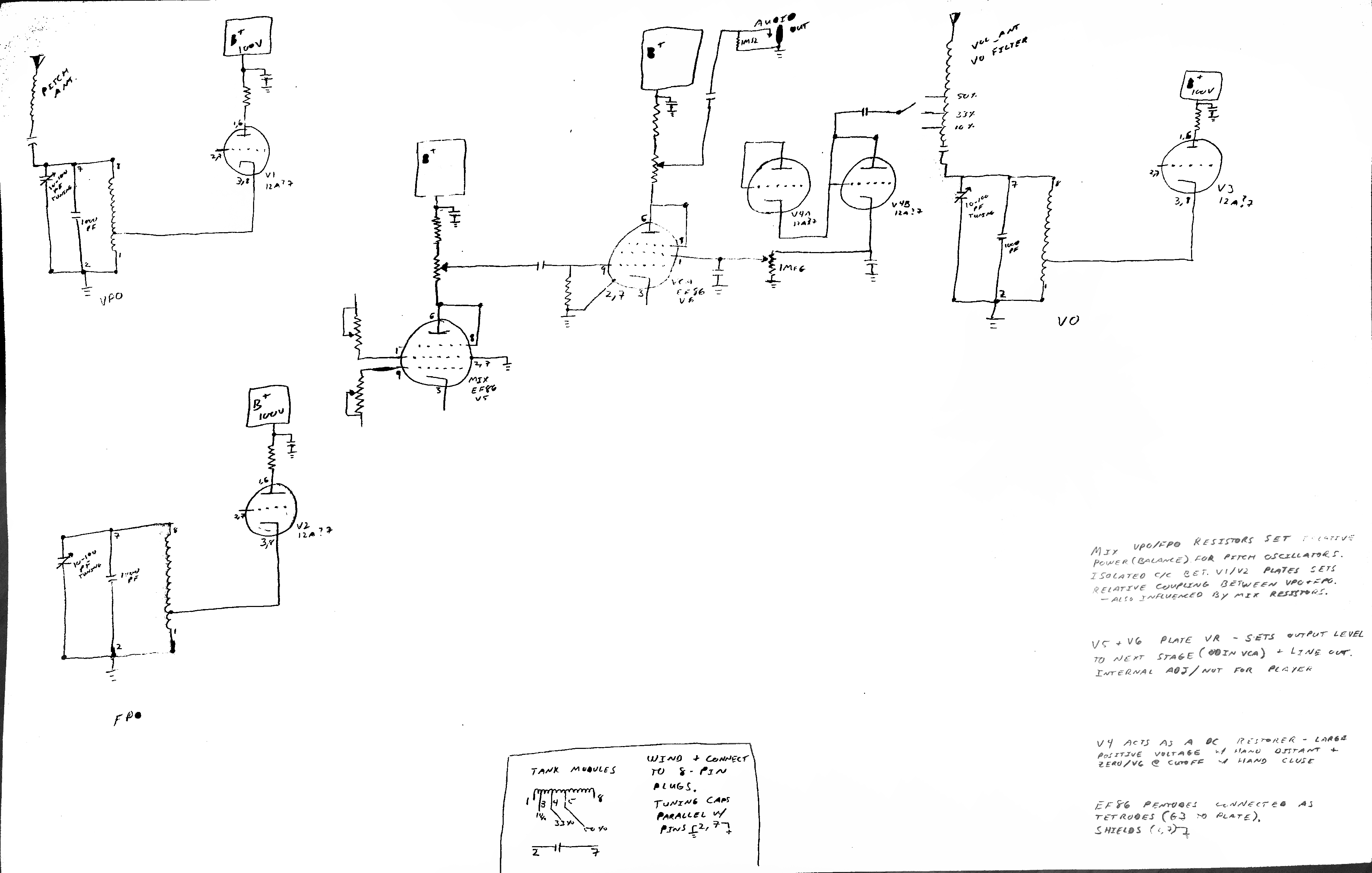
I plan to use a separate 12AX7 for each of the 3 oscillators, with both sections connected in parallel so the tube effectively functions as a single triode. Separating the pitch oscillators in this way is necessary to prevent capacitive coupling between the 12AX7 sections (I bench checked using one tube to serve as both FPO & VPO with poor results), and there's no good reason not to construct the volume oscillator identically.
Rather than the tuned plate Armstrong oscillators used in the original design I'm opting for tuned grid Hartley oscillators. This should be a distinction without a difference save for making the oscillator coils somewhat easier to wind and having the overall circuit be less twitchy and more tolerant of any poor construction on my part.
Operating frequencies will be derived from the RCA spec (170ish KHz pitch, 400ish KHz volume).
Mixer Circuit
The closest modern equivalent to the 27 tetrode would appear to be an EF86 pentode connected as a tetrode (G3 tied to the plate).
I'll be lifting the mixer circuit largely from the Rockmore theremin design, including the balancing potentiometers & variable coupling capacitor between the oscillator circuits.
Volume Control & Power Amp
Here is where I and every modern designer will be forced to break with the traditional designs: The clever variable filament power design used in the RCA themin is largely impractical today even with custom transformer winding as directly-heated (filament cathode) tubes are a rarity these days. Similarly the equally clever solution in the Rockmore theremin of driving the audio preamp's plate from a (dual)diode's cathode would require some engineering abuses of modern production tubes that I'm not 100% comfortable I could pull off.
Art's approach of varying the cathode bias is an interesting one, and I've decided to take a similar approach via a different route: I intend to use a single-ended EL84 as the power amplifier and drive the screen grid from the volume circuit (bringing the tube to cutoff when the hand is near the antenna and allowing it to conduct as the hand moves away). This design uses an additional 12AX7 family tube as a rectifier & DC restorer, feeding an essentially zero-current load on G2 of the EL84.
Variations of this approach have been used in tetrodes for other applications, though as far as I'm aware this is an untested application in the EL84 (or any beam power tube) and it is off the datasheet / not modeled in any of the tube software I have so this is going to be much of the "experimental wiggling" I mentioned. A direct lift of Art's design for the voltage-controlled amplifier is also an option should my clever twist here fail to work as desired.
Power output will be through the aforementioned EL84 (single-ended, around 10W audio output). This is somewhere between the ~0.75W you can squeeze out of the RCA's single-ended 171A and the ~15W I estimate the Rockmore circuit could produce with its push/pull 59 tubes.
That's where I stand as of this evening - looking forward to questions/comments/concerns.


